Design method for digital filter of inertial measurement unit (IMU) of mechanically-dithered laser gyroscope

A technology of machine-shaking laser gyro and inertial measurement unit, applied in the field of inertia, can solve the problems of reduced IMU measurement accuracy, large amount of computation, and large difference in output delay of IMU measurement signals.

Inactive Publication Date: 2014-12-31
BEIHANG UNIV
View PDF4 Cites 0 Cited by
  • Summary
  • Abstract
  • Description
  • Claims
  • Application Information

AI Technical Summary

Problems solved by technology

The IMU signal filtering of the machine-jittered laser gyro uses the FIR filter to obtain strict linear phase, but because the mechanical jitter noise intensity of the machine-jittered laser gyro far exceeds the useful signal strength, in order to achieve the ideal amplitude-frequency characteristics, the order of the FIR filter will be It will be very high and the amount of calculation will be large, which puts forward strict requirements on the IMU hardware system, and the group delay of the IMU output is also proportional to the order of the FIR filter, so the FIR filter makes the IMU output data delayed
The machine shaker laser gyro IMU adopts IIR filter to obtain good noise suppression effect, and the order of IIR filter is low. IIR filter includes Butterworth filter, Chebyshev type I filter, Chebyshev type II filter And the elliptic filter, the IIR filter designed according to these criteria not only has a serious phase nonlinearity, but also makes the output delay of the IMU measurement signal at different frequencies vary greatly, resulting in a decrease in the measurement accuracy of the IMU, and its group delay is also large, reducing the Real-time performance of IMU measurement

Method used


Image

  • Design method for digital filter of inertial measurement unit (IMU) of mechanically-dithered laser gyroscope
  • Design method for digital filter of inertial measurement unit (IMU) of mechanically-dithered laser gyroscope
  • Design method for digital filter of inertial measurement unit (IMU) of mechanically-dithered laser gyroscope

Examples


Embodiment Construction

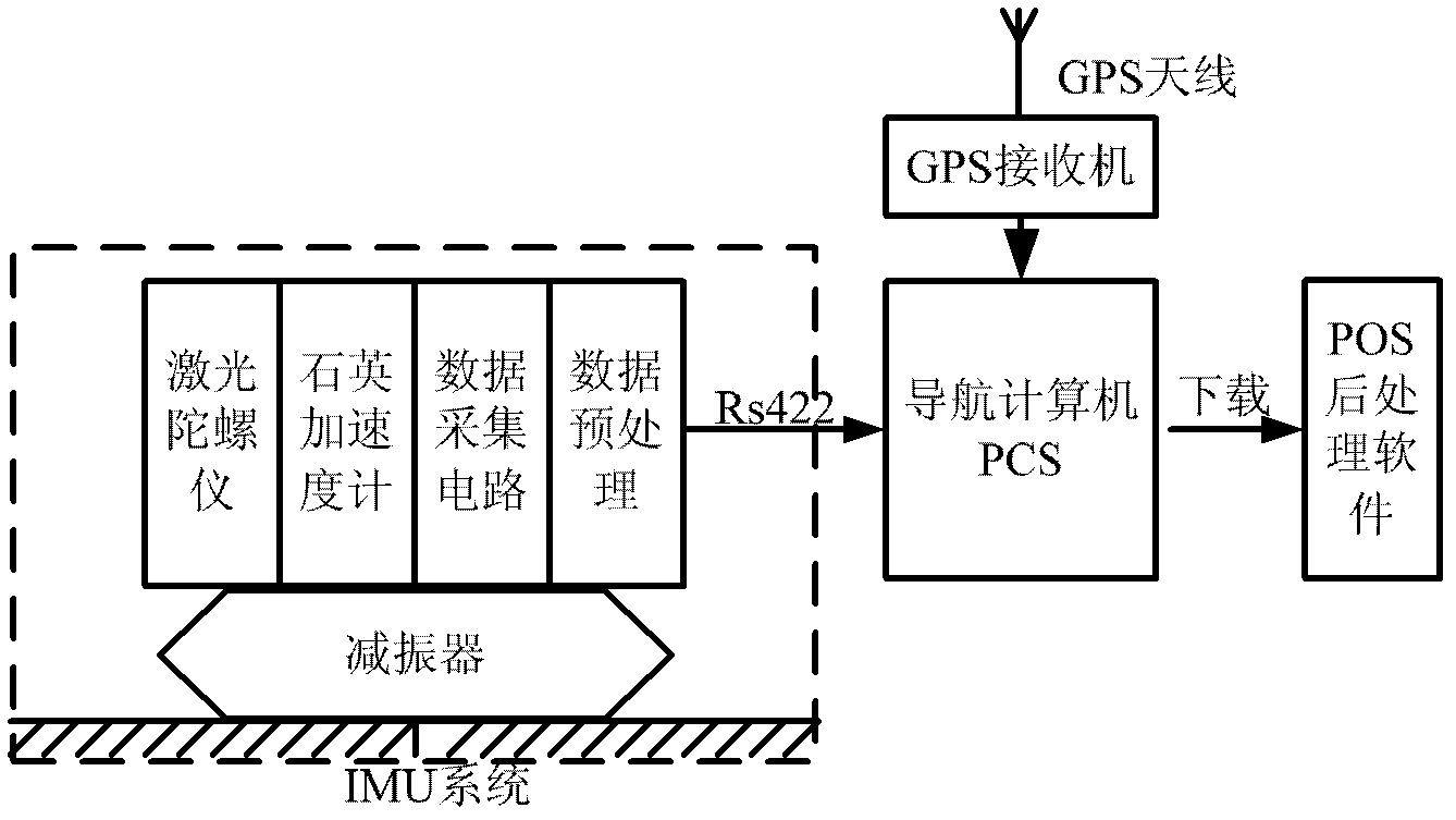
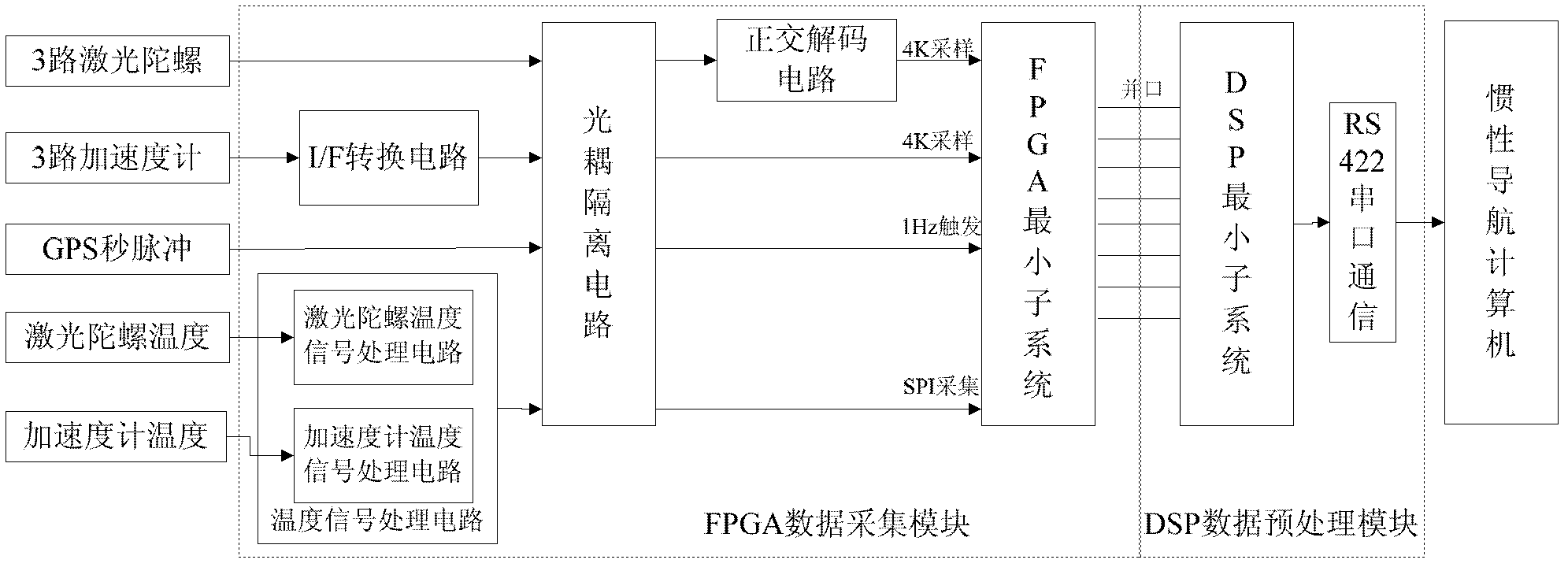
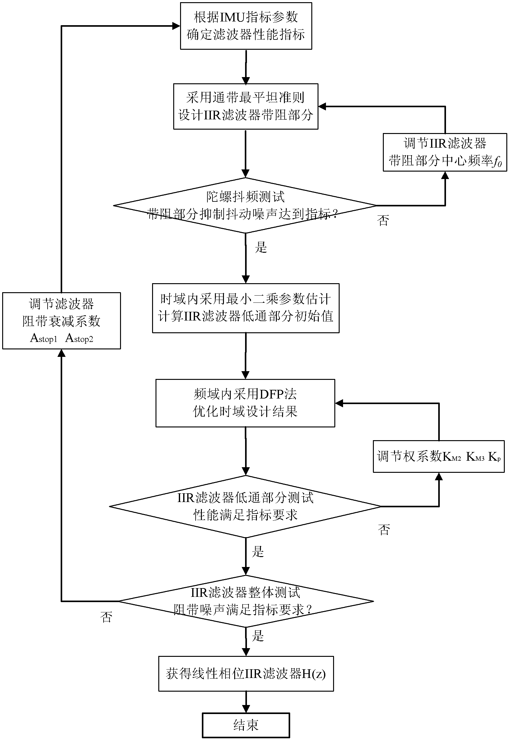
[0020] Such as figure 1 As shown, it is the POS system where the IMU, the object of implementation of the method of the present invention, is located. The IMU includes a laser gyroscope module, a quartz accelerometer module, a data acquisition circuit module and a data processing module. The filter designed by the invention is the main component of the data preprocessing module. Such as figure 2 Shown is the hardware system platform where the filter is located, the signal flow direction is marked in the figure, and the filter program will be in figure 2 Implemented in the smallest subsystem of DSP. Such as image 3 As shown, the specific implementation method is as follows:

[0021] (1) Collect the output signal of the machine-shaking laser gyro at 4KHz, and use the power spectral density analysis method to determine the peak frequency f of the machine-shaking laser gyro jitter noise n and intensity A n And the machine-shaking laser gyro frequency shaking fluctuation r...


PUM


Abstract

The invention discloses a design method for a digital filter of an inertial measurement unit (IMU) of a mechanically-dithered laser gyroscope. The invention is characterized in that the filter comprises a band-stop part and a low-pass part, and the method comprises the following steps of: firstly, designing the band-stop part of a linear phase infinite impulse response (IIR) digital filter according to the mechanically-dithered noise characteristic of the mechanically-dithered laser gyroscope; secondly, performing least square parameter estimation with forgetting factors in a time domain to make the low-pass part of the linear phase IIR digital filter approach a linear phase finite impulse response (FIR) low-pass filter, and thus obtaining an approximately linear phase; and finally, establishing a target function of the low-pass part of the linear phase IIR digital filter in a frequency domain, optimizing the target function by using a Daridon-Fletcher-Powell (DFP) method, and correcting a time domain design result to make the low-pass part of the linear phase IIR digital filter have expected frequency characteristic. The method has the advantages of approximately linear phase, low operation amount and small group delay, requirements of the filter for IMU hardware are reduced, the measurement real-time performance of the IMU is improved, time-delay compensation accuracy is ensured, and a foundation is laid for high-accuracy and real-time measurement of the IMU.

Description

technical field [0001] The invention belongs to the technical field of inertia, and relates to a design method for a digital filter of a laser gyro inertial measurement unit (IMU), which can be applied to a position and orientation measurement system (Position and Orientation System, POS) and a strapdown inertial navigation system (Strap down Navigation System, SINS), and data preprocessing of SINS / GPS (Global Position System, Global Positioning System) integrated navigation system. Background technique [0002] Inertial Measurement Unit (IMU) is the core component of inertial measurement systems such as POS, SINS, SINS / GPS, etc. The inertial measurement system is based on Newton's laws of mechanics, and uses IMU to measure the linear motion and angular motion parameters of the carrier. Under the given initial conditions, the position, velocity and attitude parameters of the carrier are calculated by computer. It is an autonomous position, velocity and attitude measurement ...

Claims


Application Information

Patent Timeline
Patent Type & Authority Patents(China)
IPC IPC(8): G01C19/72H03H17/02
Inventor 李建利陈安升房建成钟麦英
Owner BEIHANG UNIV
Why Eureka
Try Eureka