
Small-sized optical system for infrared medium wave detector

An optical system and detector technology, applied in the field of optical components, can solve the problems of limiting the transmittance of infrared optical parts, difficult to control the chromatic aberration of the infrared optical system, affecting the aberration correction ability of the optical system, etc. The effect of miniaturization and enhanced detection capability

Active Publication Date: 2012-08-01
NANJING WAVELENGTH OPTO ELECTRONICS SCI & TECH CO LTD
View PDF2 Cites 16 Cited by
  • Summary
  • Abstract
  • Description
  • Claims
  • Application Information

AI Technical Summary

Problems solved by technology

However, the longer focal length will make the chromatic aberration of the infrared optical system difficult to control
[0006] Compared with visible light materials, infrared materials have greater absorption. For example, the absorption coefficient of germanium single crystal at 3.8 μm is 1.35×10 -2 / cm; the transmittance of the infrared anti-reflection film is at least two percentage points lower than that of the visible light anti-reflection film, which greatly limits the transmittance of a single infrared optical component; therefore, under the premise of ensuring good imaging quality, the pursuit of Minimizing the number of optical parts to improve the transmittance of the infrared optical system is one of the focuses in the design of infrared cameras
However, the reduction in the number of optical parts will inevitably affect the correction ability of optical system aberrations
[0007] In many occasions, the infrared optical system with only a single field of view is far from meeting the requirements, and the dual-field infrared optical system has emerged as the times require.

Method used


Image

  • Small-sized optical system for infrared medium wave detector
  • Small-sized optical system for infrared medium wave detector
  • Small-sized optical system for infrared medium wave detector

Examples


no. 1 example

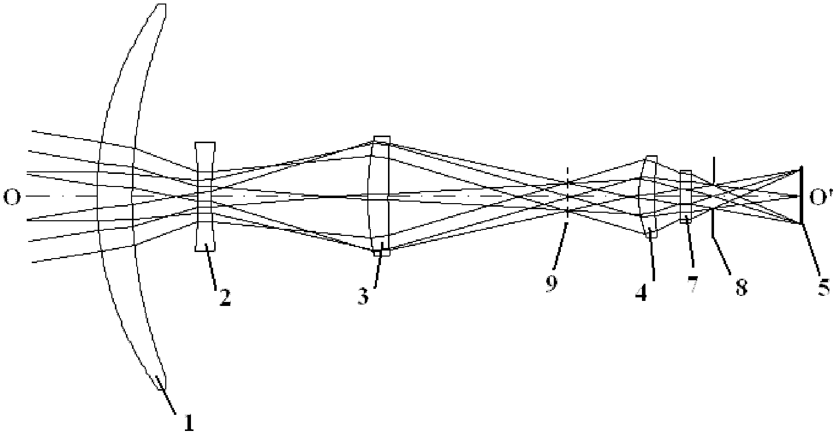
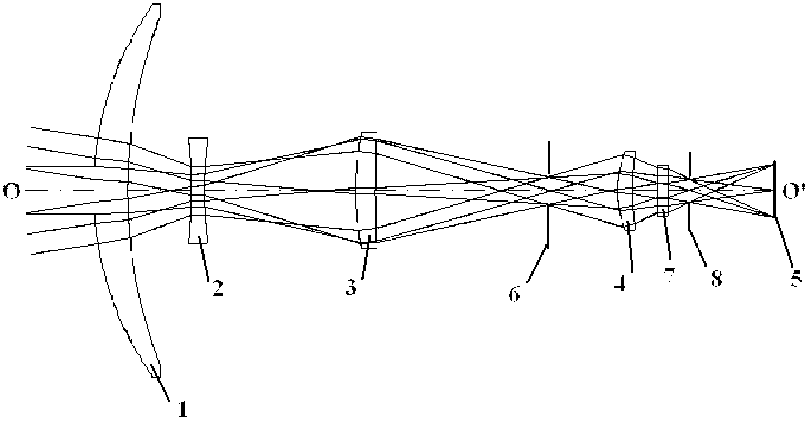
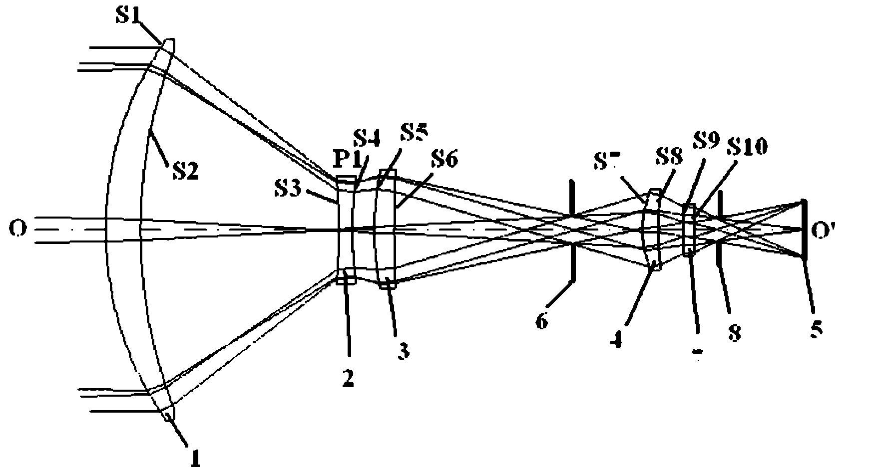
[0036] The first embodiment, such as figure 1 As shown, a small optical system for infrared mid-wave detectors includes: a first lens 1, a second lens 2, a third lens 3 and a first lens 1 arranged in sequence along the same optical axis OO' from the object point to the image point Four lenses 4, the first lens 1, the third lens 3 and the fourth lens 4 are meniscus lenses with positive refractive power and the convex surface is bent toward the object point, the second lens 2 is a biconcave lens with negative refractive power, and Based on the principle of object-image exchange, it is located in one of the two positions that make the object point and the image point conjugate, and the two positions correspond to the working state of the large field of view and the small field of view of the optical system respectively, figure 1 Only the working state of the large field of view of the optical system is drawn in the figure.

[0037] The object point is imaged for the first time a...


PUM


Abstract

The invention discloses a small-sized optical system for an infrared medium wave detector, which comprises four lenses which are sequentially arranged from an object point to an image point along the same optical axis. Focal powers of the four lenses are positive, negative, positive and positive respectively, and a second lens is located at one of two positions which enable the object point and the image point to be conjugated; the object point performs imaging for the first time at a position of an intermediate image surface between a first lens and a third lens, and an image formed for the first time is subjected to further imaging on a photosensitive surface of the infrared medium wave detector through a fourth lens; and the focal distance of the optical system is set as fn in a working state of a small field of view, the diameter of the first lens is set as D1, the focal distance of the first lens is set as f1, the magnification of the fourth lens is set as m4, then the f1 / fn is larger than or equal to 0.2 and smaller than or equal to 0.3, f1 / D1 is larger than or equal to 0.7 and smaller than or equal to 1.2, and m4 is larger than or equal to -3 and smaller than or equal to -1.5. The small-sized optical system for the infrared medium wave detector has the advantages that miniaturization of infrared cameras is achieved, and simultaneously the optical system is guaranteed to have a large aperture, a long focal distance, double fields of view, and good imaging qualities.

Description

technical field [0001] The invention relates to the technical field of optical elements, in particular to a small optical system for an infrared mid-wave detector. Background technique [0002] In recent years, infrared imaging technology and its application have been widely valued and developed vigorously in various countries. The increasing maturity of infrared focal plane detector technology provides a good foundation for meeting the needs of various fields and further promotes the development of infrared optical systems. [0003] Compared to visible light cameras, infrared cameras detect objects that are weak targets with low contrast. Target detection capability is a key indicator of infrared camera performance. The infrared camera includes an optical system and an infrared detector. Three measures can be taken to improve the detection ability of the infrared camera. One is to use a high-sensitivity cooled infrared detector; the other is to increase the effective aper...

Claims


Application Information

Patent Timeline
IPC IPC(8): G02B13/14G02B13/18G02B13/00G02B1/00G02B7/02G01J5/00
Inventor 李荣刚张兴德刘琳王弘韬殷金坚
Owner NANJING WAVELENGTH OPTO ELECTRONICS SCI & TECH CO LTD
Learn More