Flow cell frame with diversion structure, galvanic pile and processing method of galvanic pile
A flow battery and processing technology, which is applied to fuel cell components, fuel cells, regenerative fuel cells, etc., can solve problems such as cell structure deformation, reduce the probability of zinc dendrite formation on the electrode surface, etc., to simplify the structure, reduce the Mold cost and processing cost, the effect of reducing the probability of generation
- Summary
- Abstract
- Description
- Claims
- Application Information
AI Technical Summary
Problems solved by technology
Method used
Image

Examples
Embodiment 1
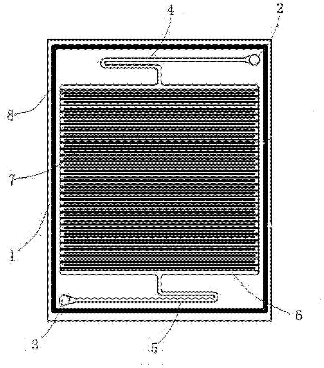
[0042] Embodiment 1 of the present invention: as figure 1 As shown, a frame of a flow battery with a diversion structure includes a frame body 1, a frame inlet 2, a frame outlet 3, an inlet shunt groove 4, and an outlet shunt groove 5, and the frame inlet 2 and the inlet shunt groove 4 are arranged on the frame body 1, the frame outlet 3 and the outlet shunt groove 5 are arranged at the bottom of the frame body 1, and the middle part of the frame body 1 is provided with an active area 6, and the active area 6 passes through the inlet shunt groove 4 and the outlet shunt groove 5 and the frame inlet 2 and the frame body respectively. The frame outlet 3 is connected; the active area 6 is provided with a diversion field 7; the frame body 1 is provided with a sealing line 8 around it. The thickness of the frame body 1 is 0.5 mm. The height of the sealing line 8 is 0.01 mm.
[0043] Such as Figure 7 As shown, the diversion field 7 is composed of ridges 15 and flow channels 16; ...
Embodiment 2
[0055] Embodiment 2 of the present invention: as figure 1 As shown, a frame of a flow battery with a diversion structure includes a frame body 1, a frame inlet 2, a frame outlet 3, an inlet shunt groove 4, and an outlet shunt groove 5, and the frame inlet 2 and the inlet shunt groove 4 are arranged on the frame body 1, the frame outlet 3 and the outlet shunt groove 5 are arranged at the bottom of the frame body 1, and the middle part of the frame body 1 is provided with an active area 6, and the active area 6 passes through the inlet shunt groove 4 and the outlet shunt groove 5 and the frame inlet 2 and the frame body respectively. The frame outlet 3 is connected; the active area 6 is provided with a diversion field 7; the frame body 1 is provided with a sealing line 8 around it. The thickness of the frame body 1 is 2mm. The height of the sealing line 8 is 0.2 mm.
[0056] Such as Figure 8 As shown, the diversion field 7 is composed of ridges 15 and flow channels 16; the ...
Embodiment 3
[0069] Embodiment 3 of the present invention: as figure 1 As shown, a frame of a flow battery with a diversion structure includes a frame body 1, a frame inlet 2, a frame outlet 3, an inlet shunt groove 4, and an outlet shunt groove 5, and the frame inlet 2 and the inlet shunt groove 4 are arranged on the frame body 1, the frame outlet 3 and the outlet shunt groove 5 are arranged at the bottom of the frame body 1, and the middle part of the frame body 1 is provided with an active area 6, and the active area 6 passes through the inlet shunt groove 4 and the outlet shunt groove 5 and the frame inlet 2 and the frame body respectively. The frame outlet 3 is connected; the active area 6 is provided with a diversion field 7; the frame body 1 is provided with a sealing line 8 around it. The thickness of the frame body 1 is 4 mm. The height of the sealing line 8 is 0.4 mm.
[0070] Such as Figure 9 As shown, the diversion field 7 is composed of ridges 15 and flow channels 16; the...
PUM
| Property | Measurement | Unit |
|---|---|---|
| Thickness | aaaaa | aaaaa |
| Height | aaaaa | aaaaa |
| Thickness | aaaaa | aaaaa |
Abstract
Description
Claims
Application Information
 - R&D
- Intellectual Property
- Life Sciences
- Materials
- Tech Scout
- Unparalleled Data Quality
- Higher Quality Content
- 60% Fewer Hallucinations
Browse by: Latest US Patents, China's latest patents, Technical Efficacy Thesaurus, Application Domain, Technology Topic, Popular Technical Reports.
© 2025 PatSnap. All rights reserved.Legal|Privacy policy|Modern Slavery Act Transparency Statement|Sitemap|About US| Contact US: help@patsnap.com