Battery cooling plate structure

A cooling plate and battery technology, applied in secondary batteries, circuits, electrical components, etc., can solve the problems of many welding points, changing flow resistance, high cost, etc., meet the temperature requirements, prolong the service life, and low manufacturing cost Effect

Active Publication Date: 2012-08-01
深蓝汽车科技有限公司
View PDF2 Cites 25 Cited by
  • Summary
  • Abstract
  • Description
  • Claims
  • Application Information

AI Technical Summary

Problems solved by technology

Due to insufficient battery performance, the battery system will release a large amount of heat during the high-current charge and discharge process and heat up. When the temperature rises to a certain level, the battery cell may have dangers such as leakage, explosion, and combustion.
[0003] At present, the heat dissipation scheme of the vehicle power battery module with moderate mixing and below mainly adopts the air-cooling method. The temperature of the cold air entering the battery module is relatively low. Due to the continuous heat absorption in the battery module, the temperature of the wind gradually increases, which will cause The inconsistency of battery heat dissipation leads to inconsistency in the working environment of the battery, which affects the life of the entire battery pack
With the emergence of strong mixing and plug-in, the requirements for battery system capacity and charge and discharge power are higher, and air cooling cannot meet the heat dissipation requirements at all. Liquid cooling with high cooling efficiency and good controllability is required.
[0004] At present, there are two main methods of liquid cooling: one is a liquid-cooled heat exchanger, which has high cooling efficiency and good controllability, but its structure cannot meet the requirements of lightness and thinness, and it cannot be integrated into a battery system with special requirements.
One is the cooling water plate spliced ​​by cooling flat tubes, which can be integrated into the battery system with special requirements, but this structure has many welding points, which reduces the reliability of the cooling water plate, and the process is complicated and the cost is high ; In addition, because the cooling flat tube cannot change the flow resistance according to actual needs, the flow field inside the cooling plate cannot be controlled, and the distribution of the flow field is uneven.

Method used


Image

  • Battery cooling plate structure
  • Battery cooling plate structure
  • Battery cooling plate structure

Examples


Embodiment Construction

[0018] The present invention will be further described below in conjunction with accompanying drawing.

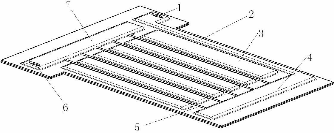
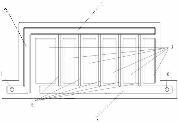
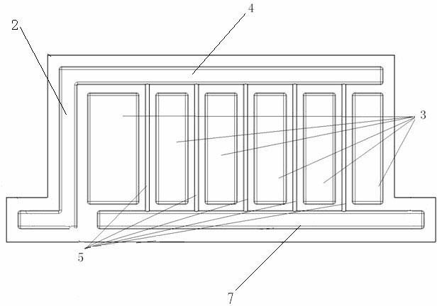
[0019] Such as figure 1 The battery cooling plate structure shown includes an upper plate and a lower plate, and the upper plate and the lower plate are welded to form a whole to form the cooling plate 10 . The upper plate and the lower plate respectively have protrusions facing opposite directions, and the protrusions form cooling passages and a plurality of cooling cavities 3 . The cooling channel is used for cooling liquid to flow therethrough, and the cooling cavity 3 is used to increase the bonding area between the cooling plate 10 and the battery module 9 . The cooling passage includes a main passage, and a plurality of branch passages 5 communicating with the main passage. The branch passages 5 and the heat dissipation cavities 3 are parallel to each other and alternately arranged at intervals. The main channel is composed of the first main channel 2, the second ma...


PUM


Abstract

The invention discloses a battery cooling plate structure, which comprises an upper plate and a lower plate, wherein the upper plate and the lower plate are welded into a whole to constitute a cooling plate; the upper plate and the lower plate are respectively provided with protrusions in opposite directions, a cooling channel and a plurality of heat-radiating cavities are formed among the protrusions, and the upper plate is provided with a water inlet and a water outlet, which are communicated with the cooling channel; the cooling channel is used for allowing cooling liquid to flow through and comprises a main channel and a plurality of branch channels communicated with the main channel; and the heat-radiating cavities and the branch channels are parallel mutually and are arranged at interval in a staggered manner. The battery cooling plate structure is simple in structure, low in manufacturing cost and simple in process and is good in controllability as a flow field structure inside the cooling plate can be distributed according to actual needs. By means of integrating the cooling plate into a power battery system of an electric vehicle, the requirement of a power battery assembly of the electric vehicle for the temperature can be better met, so that the stability of a battery system is increased and the service life of the battery system is prolonged.

Description

technical field [0001] The invention relates to a cooling technology for an electric vehicle power battery assembly, in particular to a battery cooling plate structure. Background technique [0002] Electric vehicles are required to have high-current charging and discharging performance in the battery system under the operating conditions of climbing slopes and emergency start-stops. Due to the insufficient performance of the battery, the battery system will release a large amount of heat during the high-current charging and discharging process and heat up. When the temperature rises to a certain level, the battery cell may have dangers such as leakage, explosion, and burning. [0003] At present, the heat dissipation scheme of the vehicle power battery module with moderate mixing and below mainly adopts the air-cooling method. The temperature of the cold air entering the battery module is relatively low. Due to the continuous heat absorption in the battery module, the tempe...

Claims


Application Information

Patent Timeline
Patent Type & Authority Applications(China)
IPC IPC(8): H01M10/50H01M10/613H01M10/6568
CPCY02E60/12Y02E60/10
Inventor 田雪勇李波王建民辛力李俊李宗华苏岭
Owner 深蓝汽车科技有限公司
Why Eureka
Try Eureka