

Outdoor permanent magnetic intelligent vacuum breaker
A vacuum circuit breaker and permanent magnet technology, applied in circuit devices, electrical components, etc., to achieve the effect of not easy to malfunction, saving operation links, and simple operation
Active Publication Date: 2012-08-01
HULUDAO POWER SUPPLY COMPANY OF STATE GRID LIAONING ELECTRIC POWER +2
View PDF5 Cites 5 Cited by
- Summary
- Abstract
- Description
- Claims
- Application Information
AI Technical Summary
Problems solved by technology
The circuit breaker can control the work of the outdoor vacuum circuit breaker through the combination of the combination circuit and the remote control, thus solving the technical problem of intelligent control of the vacuum circuit breaker
Method used
View moreImage
Smart ImageViewing Examples

Examples
Embodiment
[0015] The one-chip computer adopts ATMEGA128 one-chip computer.
[0016] The capacitor charging circuit uses ATMEGA16 microcontroller.
Login to View More PUM
 Abstract
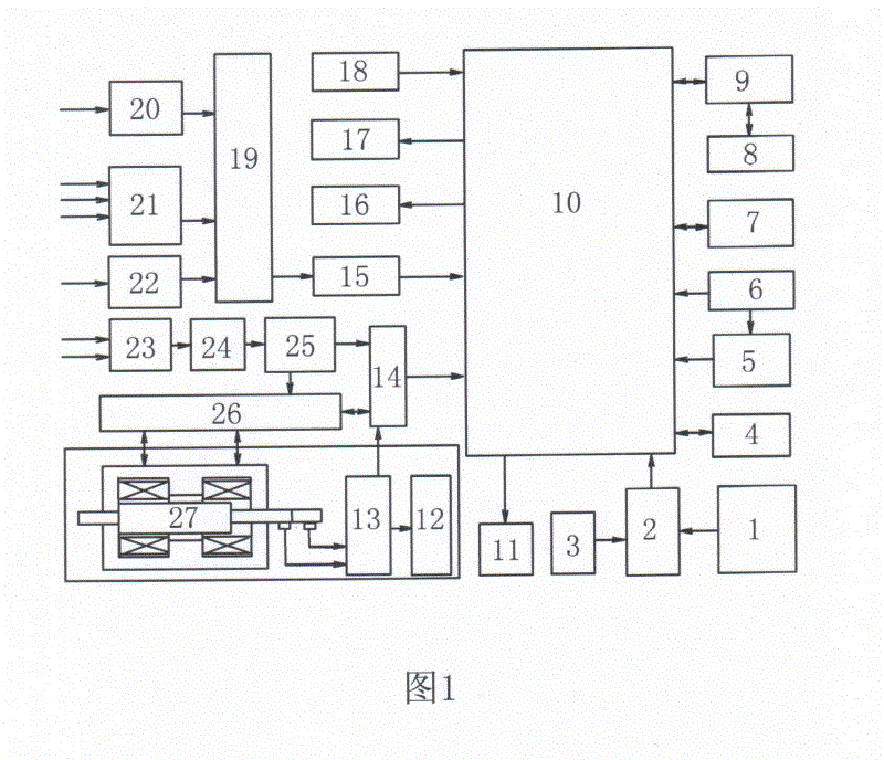
The invention relates to an outdoor permanent magnetic intelligent vacuum breaker. A zero sequence current transformer, a phase current transformer, a line voltage transformer, a filtering circuit, a power supply management circuit, a charging unit, a capacitive circuit, a photoelectric isolation circuit, a photocoupling isolation circuit, a storage unit, a watchdog circuit, a system unit circuit, a clock circuit, transistor-transistor logic (TTL) communication, a fault state alarm, a data line of an input keyboard, a liquid crystal display (LCD) and a light-emitting diode (LED) display are respectively connected onto a single-chip microcomputer. General packet radio service (GPRS) communication is connected with the TTL communication. The capacitive circuit and the photocoupling isolation circuit are connected with a driving and counter emf absorbing unit and a circuit of a permanent magnetic driver. A permanent magnetic driving circuit is provided with an in-place detecting circuit and an in-place indicator. A communication circuit is connected with the photocoupling isolation circuit, and a remote controller circuit below a column is further connected with the photocoupling isolation circuit. The outdoor permanent magnetic intelligent vacuum breaker has the advantages of being simple to operate and safe and reliable and is suitable for being used for outdoor vacuum breaker remote control operation.
Description
Technical field [0001] The invention provides a control device in the field of power transmission, specifically an outdoor permanent magnet intelligent vacuum circuit breaker. Background technique [0002] The function of the circuit breaker in the power system is to control and protect the safe and stable operation of the system. As the mainstream product of the medium voltage switch, the vacuum circuit breaker has a profound impact on the stability of the power system. [0003] However, the existing vacuum circuit breaker is usually controlled by a wired circuit, so it is prone to the disadvantages of control failure, and at the same time, it also increases the cumbersomeness of the operation. Therefore, it is prone to malfunction and cause the phenomenon of continuous disconnection. Summary of the invention [0004] In order to overcome the shortcomings of the existing vacuum circuit breaker, the present invention provides an outdoor intelligent vacuum circuit breaker. The circu...
Claims
Login to View More Application Information
Patent Timeline
 IPC IPC(8): H02J13/00
Inventor张立学郭凤仪李军王智勇李威李斌徐连洲陶宏伟刘志岭赵飞
OwnerHULUDAO POWER SUPPLY COMPANY OF STATE GRID LIAONING ELECTRIC POWER