Novel crystal oscillator circuit

A crystal oscillator and circuit technology, applied in power oscillators, electrical components, power automatic control, etc., can solve the problems of lack of flexibility in circuits, uncontrollable DC level of crystal oscillator output signals, etc., and achieve stability guarantee Effect

Inactive Publication Date: 2012-08-01
HI TREND TECH SHANGHAI
View PDF5 Cites 17 Cited by
  • Summary
  • Abstract
  • Description
  • Claims
  • Application Information

AI Technical Summary

Problems solved by technology

Although this structure is simple to implement, after the circuit starts to oscillate, the DC level of the gate and drain of the MOS transistor is always the same, resulting in uncontrollable DC level of the crystal oscillator output signal, and the circuit lacks flexibility.

Method used


Image

  • Novel crystal oscillator circuit
  • Novel crystal oscillator circuit
  • Novel crystal oscillator circuit

Examples


Embodiment Construction

[0024] In the following description, many technical details are proposed for the reader to better understand this application. However, those of ordinary skill in the art can understand that even without these technical details and various changes and modifications based on the following embodiments, the technical solutions required by the claims of this application can be implemented.

[0025] In order to make the objectives, technical solutions and advantages of the present invention clearer, the embodiments of the present invention will be further described in detail below in conjunction with the accompanying drawings.

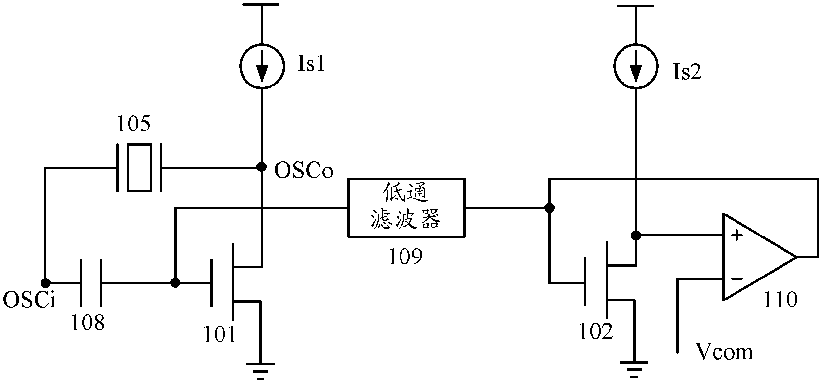
[0026] The first embodiment of the present invention relates to a new type of crystal oscillator circuit. figure 1 It is a schematic diagram of the structure of the new crystal oscillator circuit.

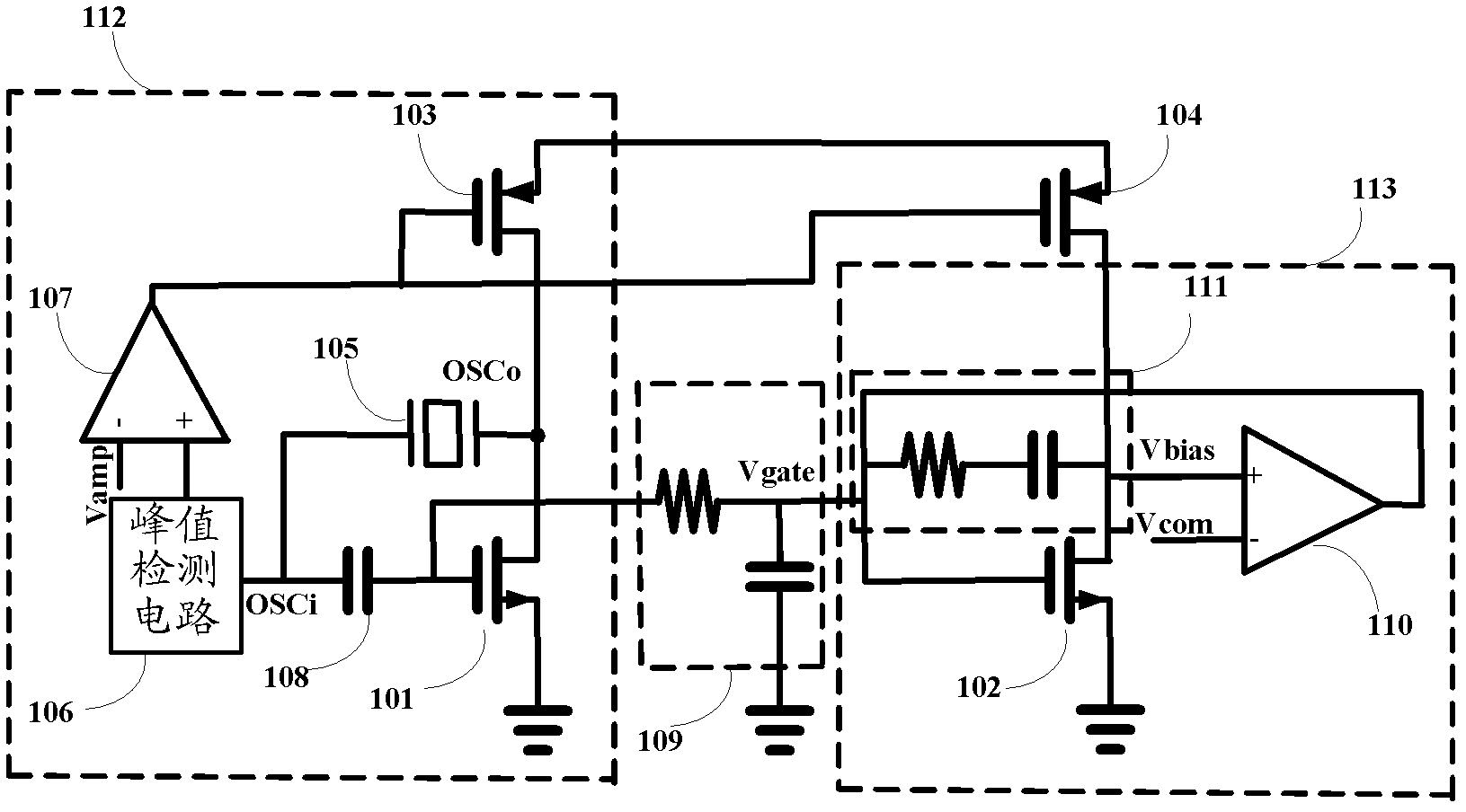
[0027] Specifically, such as figure 1 As shown, the new crystal oscillator circuit includes: a first current source Is1, a second current source Is2, a crystal oscilla...


PUM


Abstract

The invention relates to the field of circuit design, and discloses a novel crystal oscillator circuit. A principal oscillation metal-oxide-silicon (MOS) tube circuit is imaged, bias of a principle oscillation tube is indirectly controlled by controlling direct-current bias of an imaging tube, so that a direct-current level of a sinusoidal signal outputted by the crystal oscillator is biased to a preset value, control over the direct-current level of the output signal is realized, Miller compensation can be used for compensating the stability of a negative feedback control loop, and the stability of the system is guaranteed on the premise that not a very large chip area is occupied. An output signal of a peak detection circuit is compared with a second fixed level by a second operational amplifier so as to dynamically adjust a value of a bias current and to ensure that the output signal is maintained at preset amplitude.

Description

Technical field [0001] The invention relates to the field of circuit design, in particular to crystal oscillator circuits. Background technique [0002] As a basic circuit module, the crystal oscillator circuit is used in the chip to generate a precise clock signal. This clock signal can not only be mixed with the signal after frequency conversion to achieve modulation and demodulation; it can also be used as a reference clock for digital modules. Therefore, crystal oscillators exist in almost every chip and have extremely wide applications. [0003] Unlike other analog modules, the crystal oscillator takes a relatively long time to start (low-frequency crystal oscillators usually take several hundred milliseconds or even several seconds). Generally speaking, increasing the current and increasing the power consumption will shorten the start-up time, but at the same time it will increase the amplitude of the signal after the start-up. For the crystal oscillator circuit, the outpu...

Claims


Application Information

Patent Timeline
Patent Type & Authority Applications(China)
IPC IPC(8): H03B5/36H03L5/00
Inventor 韩世英马侠
Owner HI TREND TECH SHANGHAI
Why Eureka
Try Eureka