Horizontal restraint device of ballast bed

A technology of restraint device and ballast bed, which is applied in the field of rail transit, can solve the problems of insufficient lateral restraint of ballast bed structure, short ballast bed maintenance period, insufficient vertical and horizontal resistance, etc.

Inactive Publication Date: 2012-08-08
BEIJING JIAOTONG UNIV
View PDF5 Cites 9 Cited by
  • Summary
  • Abstract
  • Description
  • Claims
  • Application Information

AI Technical Summary

Problems solved by technology

[0005] The technical problem to be solved by the present invention is to overcome the problems of insufficient lateral constraints of the existing ballast bed structure, short ballast bed maintenance period, and insufficient vertical and horizontal resistance

Method used


Image

  • Horizontal restraint device of ballast bed
  • Horizontal restraint device of ballast bed
  • Horizontal restraint device of ballast bed

Examples


Embodiment Construction

[0026] The present invention will be further described in conjunction with the accompanying drawings.

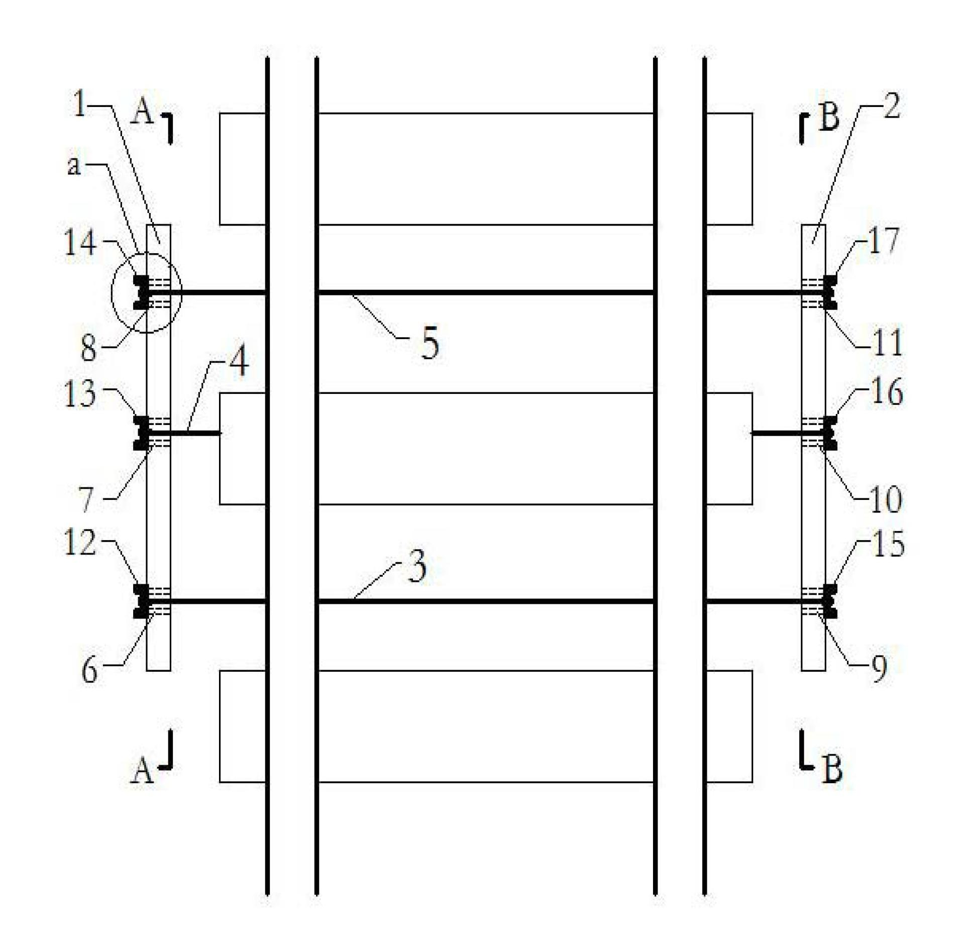
[0027] A ballast bed lateral restraint device, such as figure 1 , the device includes a reinforced concrete slab 1 on the left side of the line, a reinforced concrete slab 2 on the right side of the line, the first, second, and third wire rope slings 3, 4, 5, and the first to sixth iron casing sleeves 6, 7, 8 , 9, 10, 11, the first to sixth U-shaped bolts 12, 13, 14, 15, 16, 17.

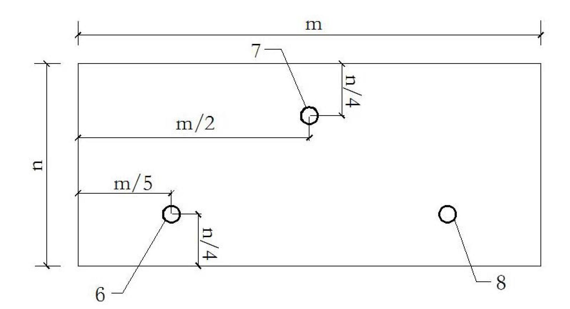
[0028] On the reinforced concrete slab 1 on the left side of the line, the first, second and third iron bushing sleeves 6, 7 and 8 are pre-embedded, such as figure 2 .

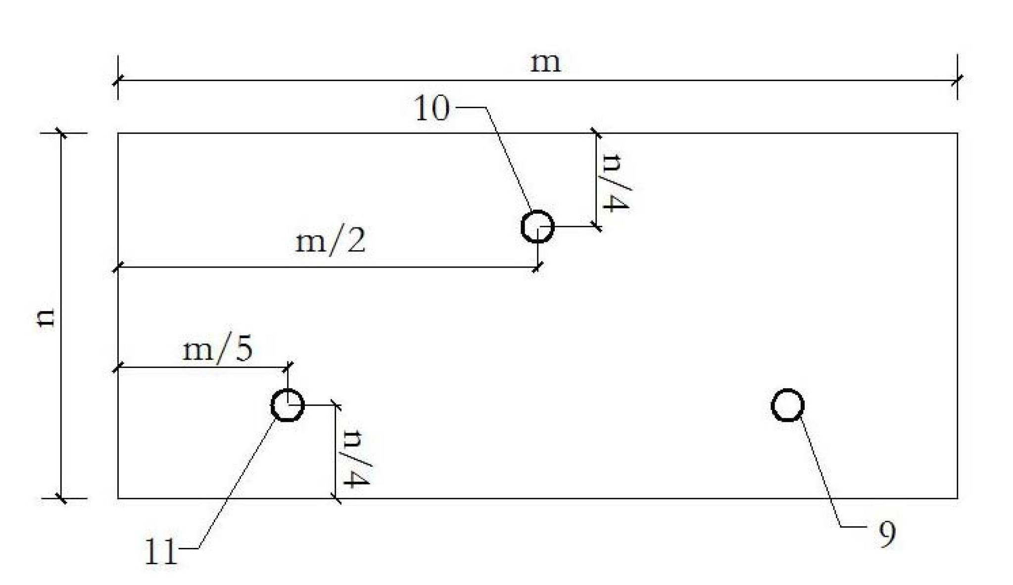
[0029] On the reinforced concrete slab 2 on the right side of the line, the fourth, fifth and sixth iron bushing sleeves 9, 10 and 11 are pre-embedded image 3 .

[0030] One end of the first wire rope rigging 3 passes through the first iron sleeve sleeve 6 on the reinforced concrete slab 1 on the left side of the line, and th...


PUM


Abstract

A horizontal restraint device of a ballast bed belongs to the field of track traffic and resolves the problems that an existing ballast bed structure is not sufficient in horizontal restraint, and a ballast bed is short in maintenance cycle and not sufficient in longitudinal and horizontal resistance. One ends of a first steel wire rope rig, a second steel wire rope rig and a third steel wire rope rig (3, 4 and 5) of the horizontal restraint device respectively penetrate through a first iron casing sleeve, a second iron casing sleeve and a third iron casing sleeve (6, 7 and 8) on a reinforced concrete plate (1) on the left side of a line. A first U-type bolt, a second U-type bolt and a third U-type bolt (12, 13 and 14) are inserted into annular connectors of one ends of the first steel wire rope rig, the second steel wire rope rig and the third steel wire rope rig (3, 4 and 5). The other ends of the first steel wire rope rig, the second steel wire rope rig and the third steel wire rope rig (3, 4 and 5) respectively penetrate through a fourth iron casing sleeve, a fifth iron casing sleeve and a sixth iron casing sleeve (9, 10 and 11) on a reinforced concrete plate (2) on the right side of the line. A fourth U-type bolt, a fifth U-type bolt and a sixth U-type bolt (15, 16 and 17) are inserted into annular connectors of the other ends of the first steel wire rope rig, the second steel wire rope rig and the third steel wire rope rig (3, 4 and 5).

Description

technical field [0001] The invention relates to a reinforcing device for a ballast bed of a ballasted track, which belongs to the field of rail transportation. It is suitable for structural reinforcement of heavy-duty or high-speed ballasted ballast beds. Background technique [0002] Ballasted track is an important part of rail transit structure. The disadvantages of ballasted track structure maintenance are: [0003] 1. In the high-speed railway, the vibration is strengthened in the bridge and tunnel section. Due to the lack of lateral restraint, the ballast is easy to fluidize, collapse, and the geometric size changes; [0004] 2. For heavy-duty lines, due to the huge dynamic effect of the train and insufficient lateral restraint, the ballast particles are easily broken and pulverized, resulting in increased maintenance costs; the vertical and lateral resistance of the ballast bed in curved sections is likely to be insufficient, and the track is prone to instability. C...

Claims


Application Information

Patent Timeline
Patent Type & Authority Applications(China)
IPC IPC(8): E01B1/00
Inventor 刘亮曹小虎靳瑾赵益陈晓庆
Owner BEIJING JIAOTONG UNIV
Why Eureka
Try Eureka