Medium-temperature foil type resistance strain gauge

A resistance strain gauge, foil-type technology, applied in the field of medium-temperature foil resistance strain gauge, can solve the problems of increased discreteness of strain gauge measurement data, drift of strain gauge output signal, and deterioration of strain gauge stability, etc., to achieve improved Stability and reliability, good consistency of measurement accuracy, effect of improving measurement accuracy

Active Publication Date: 2012-08-15
ZHONGHANG ELECTRONICS MEASURING INSTR
View PDF4 Cites 9 Cited by
  • Summary
  • Abstract
  • Description
  • Claims
  • Application Information

AI Technical Summary

Problems solved by technology

The medium temperature foil resistance strain gauge is a measuring instrument component used in the temperature range of 60°C to 300°C. However, up to now, this kind of strain gauge has always had relatively large defects. Specifically, when the measurement environment temperature exceeds 120°C When , the stability of the strain gauge becomes worse, the measurement accuracy decreases, and the error increases
Through in-depth research, it is found that the reason for the above problems is that the base and sealing layer of the existing medium-temperature foil resistance strain gauge are made of polyimide material, and the sensitive grid is made of copper-nickel al...

Method used


Image

  • Medium-temperature foil type resistance strain gauge
  • Medium-temperature foil type resistance strain gauge
  • Medium-temperature foil type resistance strain gauge

Examples


Embodiment Construction

[0016] The present invention will be further described below in conjunction with the accompanying drawings.

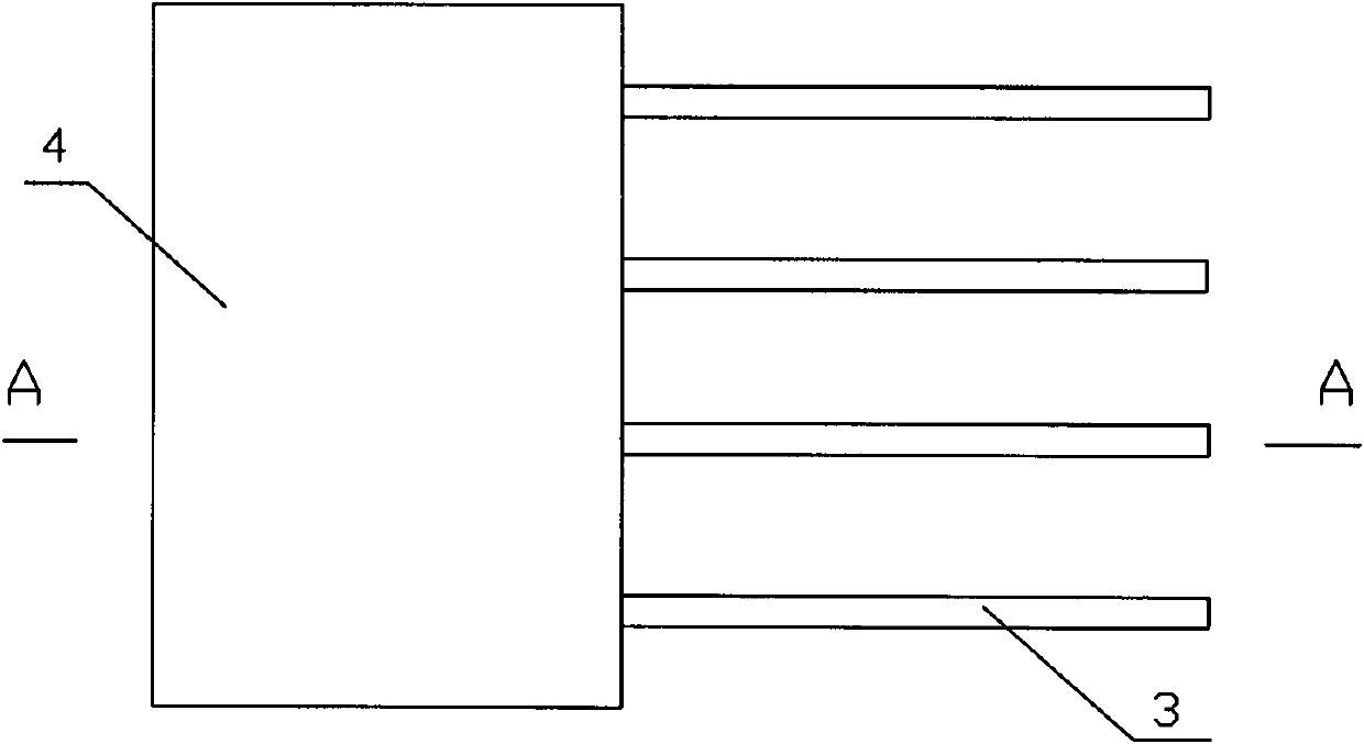
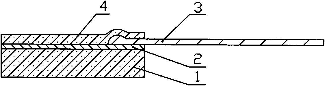
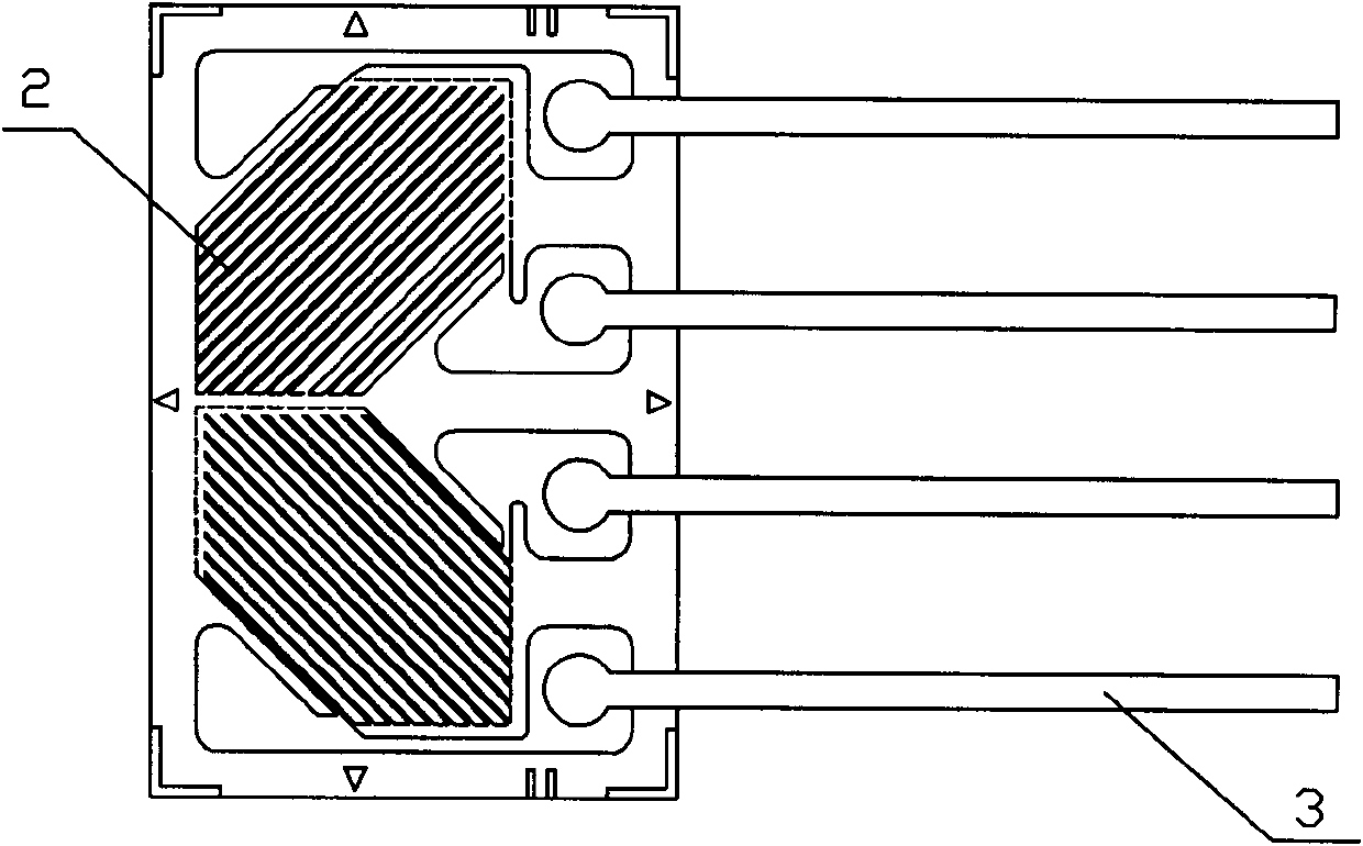
[0017] Such as figure 1 and figure 2 As shown, the strain gauge of this embodiment is composed of a glass fiber reinforced polyimide base 1 , a sensitive grid 2 and a polyimide sealing layer 4 , and the sensitive grid 2 is firmly attached between the base 1 and the sealing layer 4 .

[0018] In the manufacturing process, the copolymerized aromatic polyimide glue is first mixed with the surface-treated quartz filler and nano-scale silicon powder, and the mixed glue is coated on the Karma alloy foil or Ewen alloy foil or nickel-chromium The back of the alloy foil, and then spread a layer of glass fiber on the mixed rubber surface, and then form a strain gauge substrate with metal foil by high temperature heating and pressure, and the glass fiber reinforced polymer on the substrate The imide part is the substrate 1 of the strain gauge; the formation of the sensitive gr...


PUM

PropertyMeasurementUnit
Thicknessaaaaaaaaaa
Thicknessaaaaaaaaaa
Thicknessaaaaaaaaaa

Abstract

The invention discloses a medium-temperature foil type resistance strain gauge. The medium-temperature foil type resistance strain gauge comprises a substrate, a sensitive grid and a sealing layer, wherein the sensitive grid is firmly adhered to the substrate and is sealed by the sealing layer; the substrate is made of an enhanced polyimide composite material or an enhanced organic silicon resin composite material; the sensitive grid is made of a Karma alloy, an Even alloy or a nickel-chromium alloy; and the sealing layer is made of polyimide or an organic silicon resin material. The medium-temperature foil type resistance strain gauge improves the stress-strain measurement accuracy in a medium-temperature environment, and the average heat output coefficient of the strain gauge is controlled in a range of 2 mu epsilon/DEG C; in the medium-temperature environment, the strain gauge has stable properties such as relative sensitivity coefficient, creep deformation and the like, can stably measure signals, and has the functions of creep deformation self-compensation and elasticity modulus self-compensation; the aging resistance and oxidation resistance of the materials of the substrate and sealing layer of the strain gauge are improved in the medium-temperature environment; and the adaptive temperature range can be expanded to be between -30 and 400 DEG C, and the consistency of the measurement accuracy is good.

Description

technical field [0001] The invention relates to a foil-type resistance strain gauge, in particular to a medium-temperature foil-type resistance strain gauge suitable for a temperature range of 60°C to 300°C. Background technique [0002] With the continuous development of science and technology, the application fields of foil resistance strain gauges have been very extensive. At the same time, people have higher and higher requirements for the measurement performance of strain gauges. The medium temperature foil resistance strain gauge is a measuring instrument component used in the temperature range of 60°C to 300°C. However, up to now, this kind of strain gauge has always had relatively large defects. Specifically, when the measurement environment temperature exceeds 120°C When , the stability of the strain gauge becomes worse, the measurement accuracy decreases, and the error increases. Through in-depth research, it is found that the reason for the above problems is that...

Claims


Application Information

Patent Timeline
IPC IPC(8): G01B7/16
Inventor 晏志鹏任博哲赵家辉熊英吴梅雷磊
Owner ZHONGHANG ELECTRONICS MEASURING INSTR
Why Eureka
Try Eureka