Debugging-free circular waveguide screw circular polarizer

A circular polarizer and circular waveguide technology, applied in waveguide-type devices, electrical components, circuits, etc., can solve the problems of difficult to achieve high performance requirements, large debugging workload, difficult processing tolerances, etc. Good processing consistency and the effect of ensuring processing accuracy

Inactive Publication Date: 2012-08-15
10TH RES INST OF CETC
View PDF3 Cites 9 Cited by
  • Summary
  • Abstract
  • Description
  • Claims
  • Application Information

AI Technical Summary

Problems solved by technology

[0006] The task of the present invention is to provide a simple structure, no need for debugging, easy to ensure processing accuracy, and consistent processing for the traditional circular waveguide circular pola

Method used


Image

  • Debugging-free circular waveguide screw circular polarizer
  • Debugging-free circular waveguide screw circular polarizer
  • Debugging-free circular waveguide screw circular polarizer

Examples


Embodiment Construction

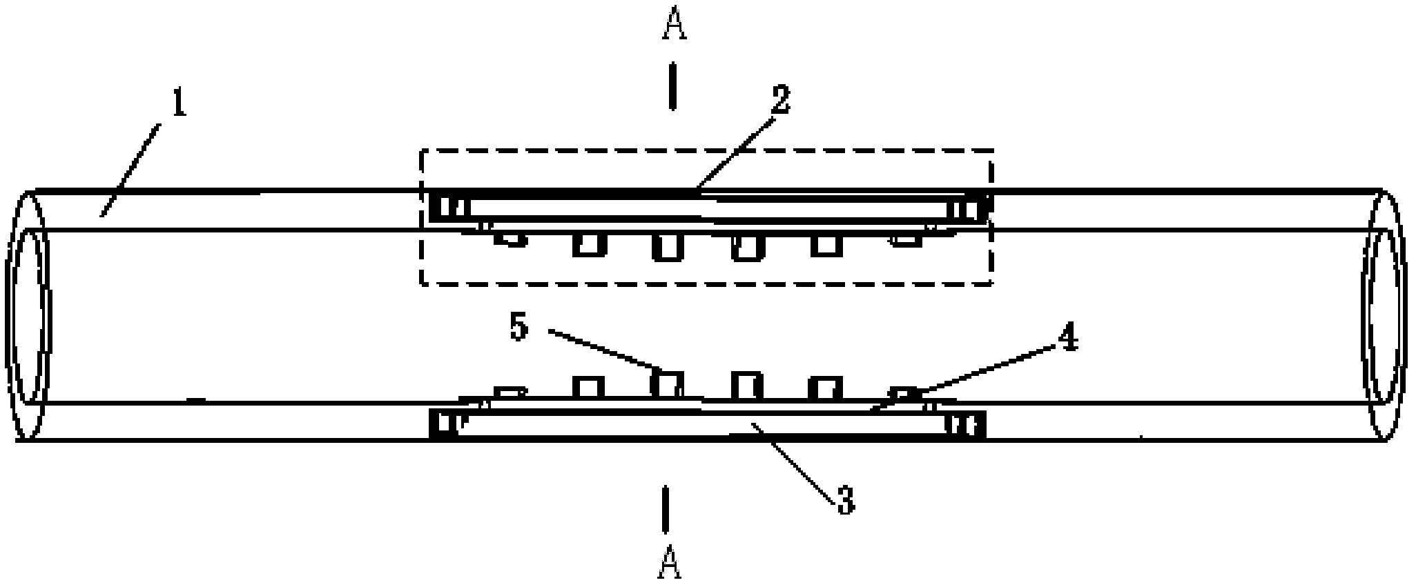
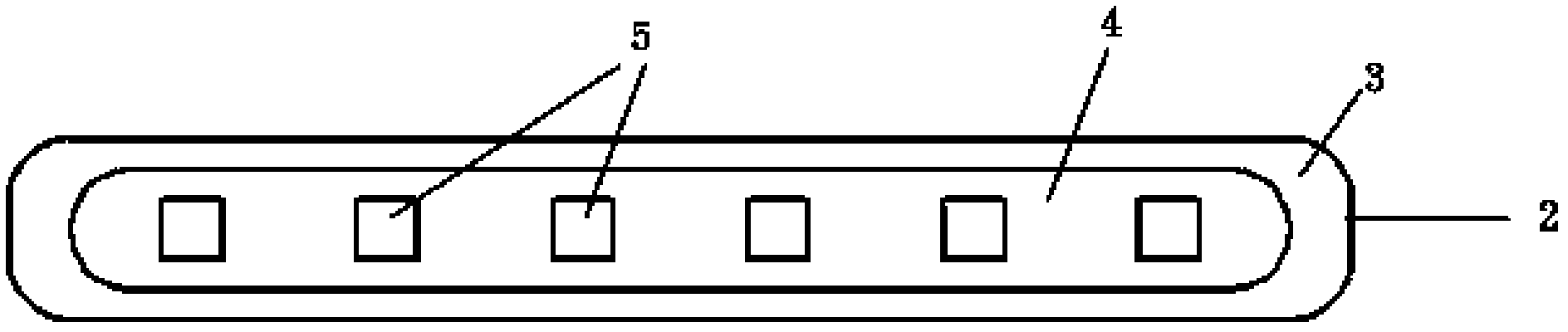
[0014] refer to figure 1 and figure 2 . figure 1 A cylindrical waveguide 1 using metal screws as phase modulating elements is described, and two rows of bidirectionally symmetrical metal integral boss mounting plates 3 on the metal wall of the cylindrical waveguide 1 cavity are placed in the circular waveguide, which constitutes the metal waveguide of the present invention. A best embodiment of screw circular waveguide circular polarizer.

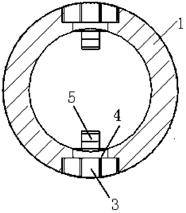
[0015] On the metal wall of the cylindrical waveguide 1, there are grooves symmetrically facing the center line of the cylindrical waveguide 1 in the radial direction, and the grooves are for assembly. image 3 As shown, the metal wall of the cylindrical waveguide (1) is made with a groove symmetrically facing the center line of the cylindrical waveguide (1) in the radial direction, and the groove is an integral component for assembling the metal integral boss mounting plate (3) , longitudinal grooves of complementary structure with the...


PUM


Abstract

The invention discloses a debugging-free circular waveguide screw circular polarizer. A metal wall of a cylindrical waveguide cavity is provided with integral boss mounting plates which are fixedly linked to a cylindrical waveguide body with the same arc; each boss mounting plate is provided with screw group phase regulating elements which are in sinusoidal distribution in height and are arrayed at intervals on a boss plane; and each integral boss mounting plate manufactured with the screw group phase regulating elements faces radially towards a cylindrical waveguide central line symmetrically, thereby forming the circular waveguide screw circular polarizer. According to the invention, through utilizing the structures of the screw group phase regulating elements which are in sinusoidal distribution and are arrayed at intervals on the radially symmetrical integral boss mounting plates, the conversion from microwave linear polarization to circular polarization is realized, the structure is simple, the loss consumption is less, and the power capacity is great. The integral screw group structure can be integrally manufactured and completed through the integral boss mounting plate of which the manufacturing accuracy is easy to ensure and manufacturing consistency is good, and the problems that the requirements for manufacturing tolerance by a millimeter wave high-performance circular polarizer are very rigorous, and the manual debugging difficulty is great are solved.

Description

technical field [0001] The invention relates to a millimeter-wave circular waveguide circular polarizer with a novel structure, and is especially suitable for designing and processing a high-precision, high-performance circular waveguide circular polarizer in the millimeter wave band. Background technique [0002] With the development of satellite communication, remote control and telemetry technology, the expansion of radar application range, and the needs of tracking and measuring high-speed targets in various polarization modes and climatic conditions, it is difficult for a single polarization mode to meet the requirements of electronic equipment. The application of the antenna becomes very important. Therefore, in antenna systems such as satellite communications, terrestrial microwave radio communications, radar antennas, and radio astronomy telescopes, circular polarizers are usually used to achieve linear / circular polarization conversion. Since the circular polarizer ...

Claims


Application Information

Patent Timeline
IPC IPC(8): H01P1/17H01Q15/24
Inventor 刘熠志侯利军刘波
Owner 10TH RES INST OF CETC
Why Eureka
Try Eureka