
Tool path generation method and device

A tool path and target point technology, applied in the field of tool path formation, can solve the problems of inconsistent tool paths and inability to obtain a smooth machined surface, and achieve the effect of smooth machined surface

Inactive Publication Date: 2012-08-15
MAKINO MILLING MASCH CO LTD
View PDF6 Cites 7 Cited by
  • Summary
  • Abstract
  • Description
  • Claims
  • Application Information

AI Technical Summary

Problems solved by technology

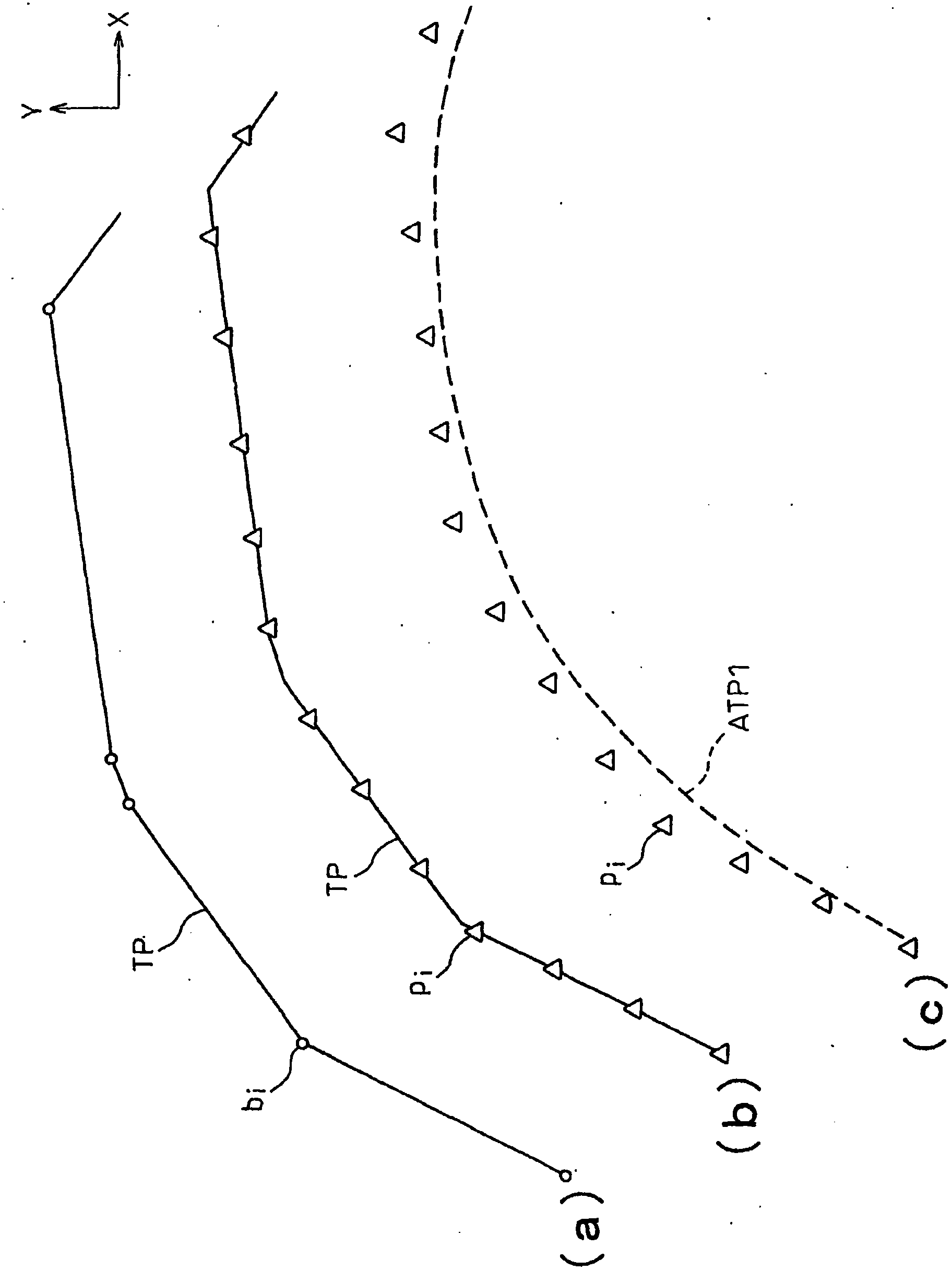
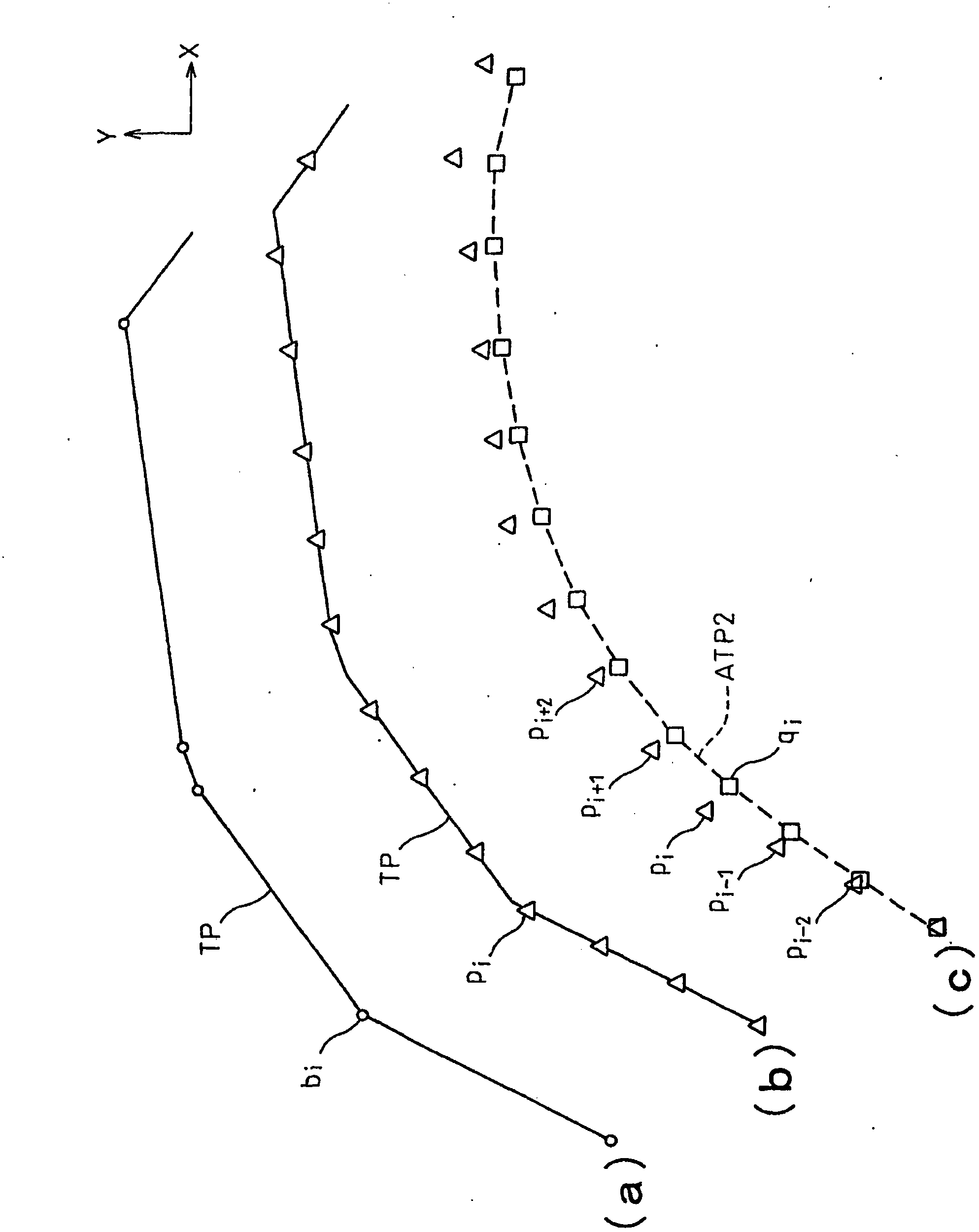
As a result, when machining a curved surface, adjacent tool paths before and after do not match, and a step difference occurs between adjacent tool paths, making it impossible to obtain a smooth machined surface.

Method used


Image

  • Tool path generation method and device
  • Tool path generation method and device
  • Tool path generation method and device

Examples


Embodiment Construction

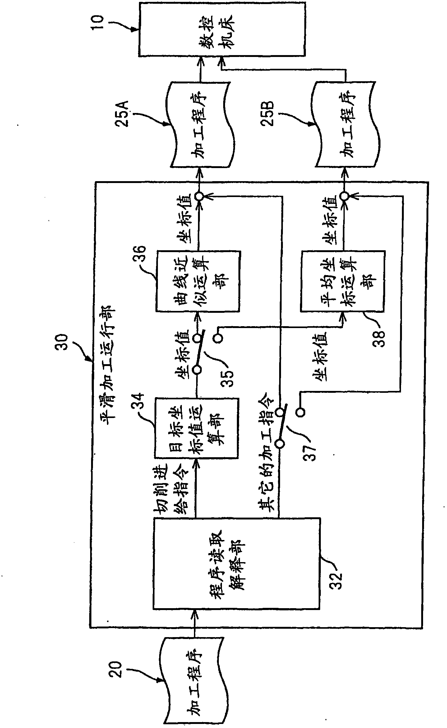
[0023] The tool path forming device of the present invention is not limited to the form of the control device 15 used together with the numerical control machine tool 10 shown in this specification, and may also be used as a CAM device that creates a machining program based on the CAD data of the workpiece, and has a built-in control device. It can be used in the form of a CNC machine tool or a personal computer. The control device 15 can perform smoothing processing after reading the machining program created by the CAM device to form a tool path, and rewrite the machining program 20 based on the formed tool path. The rewritten machining programs 25A, 25B are stored in a memory in the device, and can be read out to be used by other machine tools, or to partially edit the contents of the machining programs. In addition, the apparatus may be configured so as not to have the function of rewriting the machining program or the function of storing the machining program. The contro...


PUM


Abstract

Disclosed is a device that generates tool paths for machining a work piece with machine tools, the device comprising a program loading interpreter that reads out a tool path from a machining program, a target coordinate value computation unit that sets a plurality of equidistant target points upon the tool path thus read out, and a curve approximation computation unit that generates the tool path on the basis of the plurality of target points, in order to facilitate obtaining a smoothly machined surface without discontinuities arising between adjacent tool paths.

Description

technical field [0001] The invention relates to a method and a device for forming a tool path for machining a workpiece by a machine tool. Background technique [0002] The machining program contains movement commands relative to the feed axis of the machine tool. Position information is included in the movement command, and the tool is relatively moved to a predetermined position with respect to the workpiece at a predetermined speed, thereby processing the workpiece according to a predetermined shape. The movement path of the tool, that is, the tool path is created by converting CAD data, which is information on a workpiece drawing, into line information by a CAM device. In the machining program created by the CAM device, the coordinate value of the movement destination is included for each block. In this specification, the coordinate value of the movement command of this machining program is called a block end point. [0003] In recent years, machine tools that operate...

Claims


Application Information

Patent Timeline
Patent Type & Authority Applications(China)
IPC IPC(8): G05B19/4103B23Q15/00G05B19/4093
CPCG05B19/4103G05B2219/34143G05B19/4099B23Q15/00
Inventor 田沼匡史尾田光成小森隆
Owner MAKINO MILLING MASCH CO LTD
Learn More