
Simple measurement device for oil field well-head liquid levels
A technology of measuring device and wellhead fluid, which is applied in the directions of surveying, wellbore/well components, earthwork drilling, etc., can solve problems such as affecting oil well production, oil well production stoppage, etc., and achieve convenient and reliable measurement, easy portability, and simple operation.
- Summary
- Abstract
- Description
- Claims
- Application Information
AI Technical Summary
Problems solved by technology
Method used
Image

Examples
Embodiment Construction
[0014] The present invention will be further described below in conjunction with accompanying drawing:
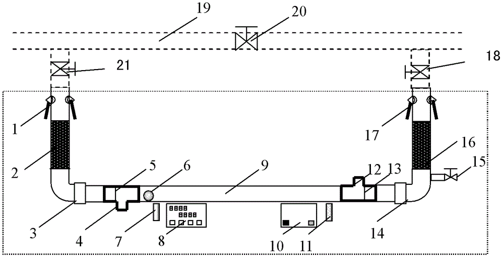
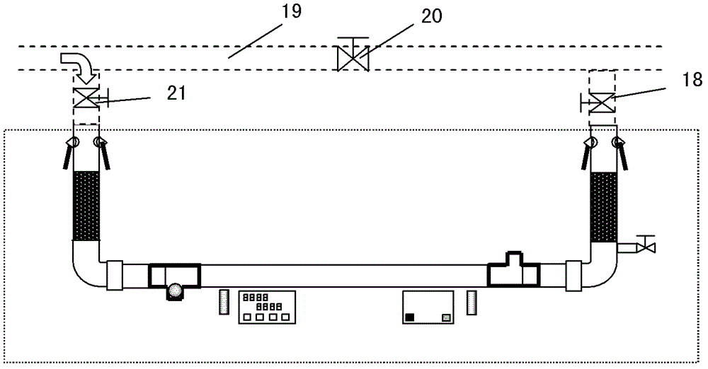
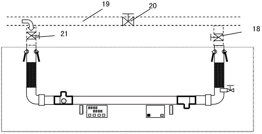
[0015] Depend on figure 1 As shown, this simple measuring device for wellhead fluid in oil fields consists of a quick connector 1 at the left end of the oil well bypass valve, a quick connector 17 at the right end, a hose 2 at the left end, a hose 16 at the right end, a rotary joint 3 at the left end, and a rotary joint 14 at the right end. And the ball-holding tee 4 at the left end, the ball-holding tee 12 at the right end, and the DC inductive proximity switch 7 at the left end, the DC inductive proximity switch 11 at the right end, and the non-metallic round pipe 9, the metal ball 6, the speedometer 8, and the DC power supply 10 and pressure relief valve 15 constitute. Among them, the left and right end ball tees are respectively equipped with left retaining wire 5 and right retaining wire 13, oil well bypass valve left and right end quick joints, left and right end hos...
PUM
 Abstract
Description
Claims
Application Information