
Optical pulse detection and protection circuit for fiber laser

A fiber laser and protection circuit technology, which is applied in the direction of instruments, can solve the problems of pulsed laser fiber burnout, etc., and achieve the effect of protecting doped fiber burnout and other optical devices from being damaged

Active Publication Date: 2012-08-22
WUHAN RAYCUS FIBER LASER TECHNOLOGY CO LTD
View PDF5 Cites 5 Cited by
  • Summary
  • Abstract
  • Description
  • Claims
  • Application Information

AI Technical Summary

Problems solved by technology

However, if the seed source leaks the pulse signal or the frequency is incomplete, it will also cause the pulsed laser to burn out the fiber.

Method used


Image

  • Optical pulse detection and protection circuit for fiber laser
  • Optical pulse detection and protection circuit for fiber laser

Examples


Embodiment Construction

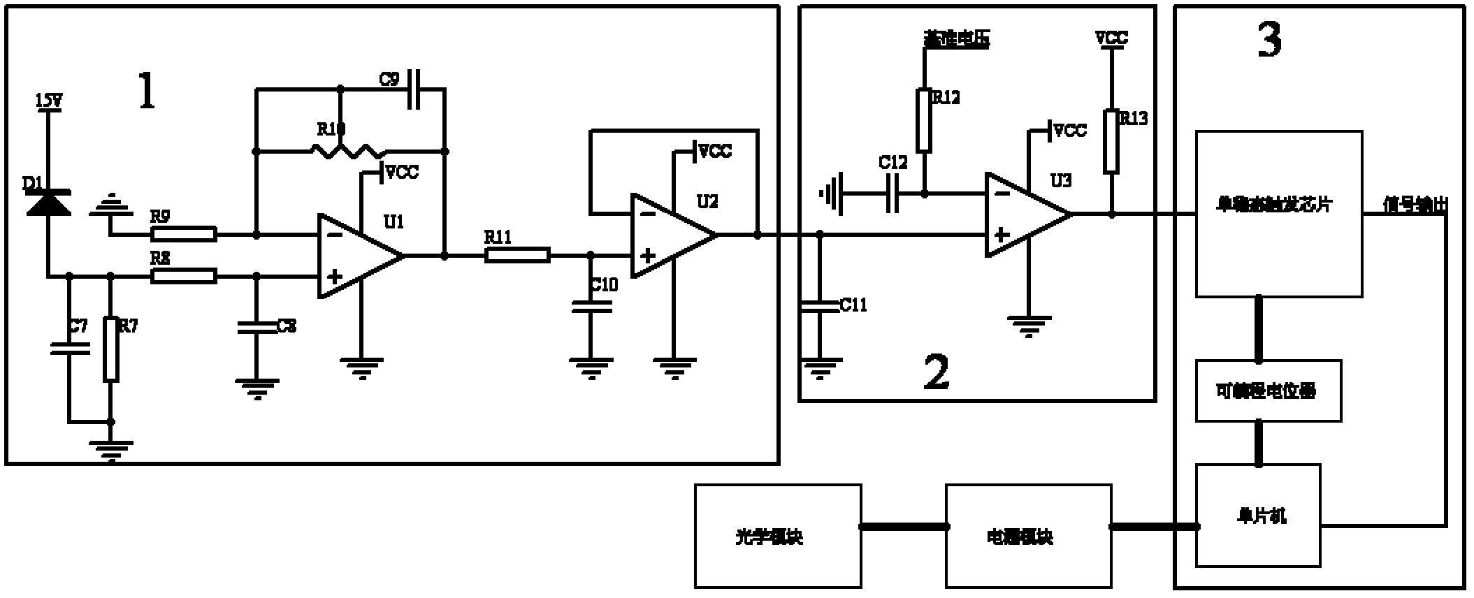
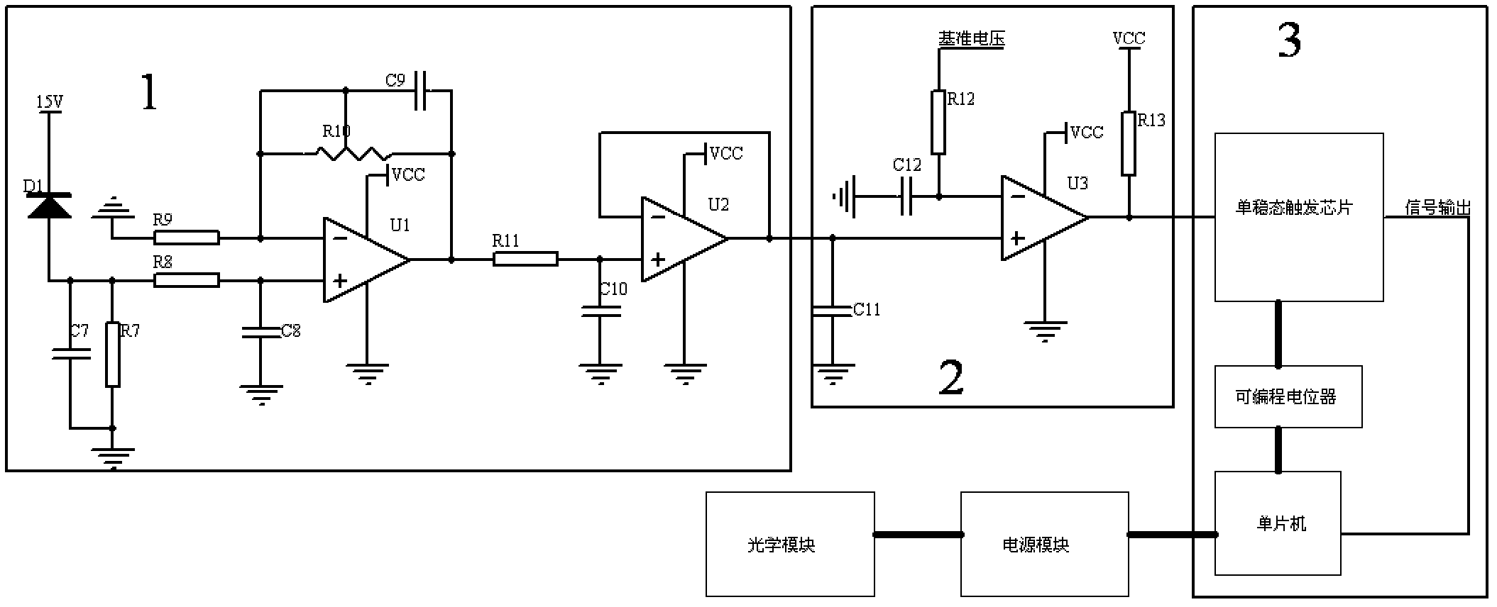
[0012] Such as figure 1 As shown, the present invention includes an optical pulse signal amplifying circuit 1, a comparison circuit 2, and a monostable trigger circuit 3. The input end of the optical pulse signal amplifying circuit 1 is connected to the output end of the photoelectric detection diode of the fiber laser, and the optical pulse signal amplifying circuit 1 The output terminal is connected with the input terminal of the comparison circuit 2, the output terminal of the comparison circuit 2 is connected with the input terminal of the monostable trigger circuit 3, and the output terminal of the monostable trigger circuit 3 is connected with the single-chip microcomputer of the monostable trigger circuit, and the monostable trigger circuit The single chip microcomputer of the trigger circuit is connected with the power module of the fiber laser, and the power module of the fiber laser is connected with the optical module of the fiber laser. The single-chip microcompute...


PUM


Abstract

The invention relates to an optical pulse detection and protection circuit for a fiber laser, which comprises an optical pulse signal amplifying circuit, a comparison circuit and a monostable trigger circuit. The optical pulse signal amplifying circuit is connected with the monostable trigger circuit through the comparison circuit, the monostable trigger circuit changes charge-discharge time of amonostable trigger chip by setting the resistance value of a programmable potentiometer under different frequencies through a single chip microcomputer, accordingly, whether compared optical pulse digital signals are normal or not is detected, and the monostable trigger circuit outputs TTL (transistor-transistor logic) low level if the optical pulse digital signals are abnormal, and outputs TTL high level if the optical pulse digital signals are normal. The single chip microcomputer detects output signals of the monostable trigger circuit, and a power supply is immediately turned off once thesingle chip microcomputer detects that the monostable trigger circuit outputs the TTL low level, so that iridium-doped fibers are protected from excessive burnout. The optical pulse detection and protection circuit functions in protecting the pulse laser in real time, so that the pulse laser can be effectively prevented from failing and burning the iridium-doped fibers.

Description

technical field [0001] The invention relates to an optical pulse detection and protection circuit for a fiber laser. Background technique [0002] Due to many advantages such as low price, compact structure, high efficiency, narrow line width, and tunable wavelength, Q-switched double-clad fiber lasers are widely used in many fields such as remote sensing, ranging, medical, military, industrial processing, nonlinear optical applications, etc. widely used. [0003] At present, the fiber laser protection circuit is realized by detecting the average value of the optical pulse signal. This solution is to amplify the optical signal and then convert the optical pulse signal to a DC signal, and compare it with a set reference point to realize the protection of the pulsed laser. This protection can only be used for those with no optical signal output Only in this case can it play a protective role. However, if the seed source leaks the pulse signal or the frequency is incomplete,...

Claims


Application Information

Patent Timeline
IPC IPC(8): G01J11/00
Inventor 闫大鹏李成刘晓旭黄荣
Owner WUHAN RAYCUS FIBER LASER TECHNOLOGY CO LTD
Learn More