Frame sealing glue width detecting method, system and equipment
A technology of sealing glue and glue width, applied in the direction of measuring devices, optics, instruments, etc., can solve the problems of detection time delay, loss, and inability to adjust the sealing glue coating equipment in time, so as to shorten the time delay and improve the timely sexual effect
- Summary
- Abstract
- Description
- Claims
- Application Information
AI Technical Summary
Problems solved by technology
Method used
Image

Examples
Embodiment 1
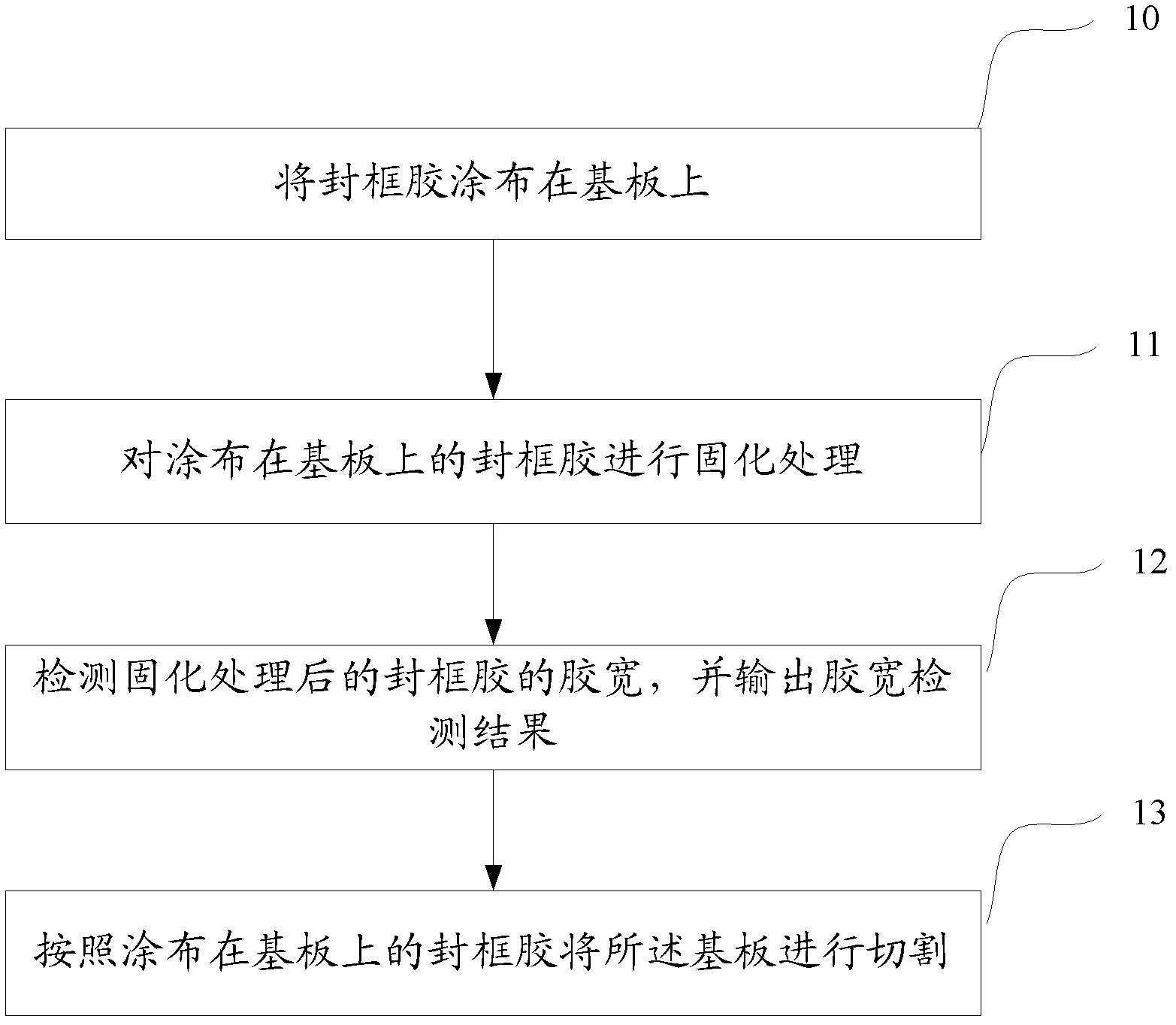
[0059] Step 1: The glue applicator applies the sealant on the substrate;
[0060] Step 2: The thermal curing furnace cures the frame sealant coated on the substrate;
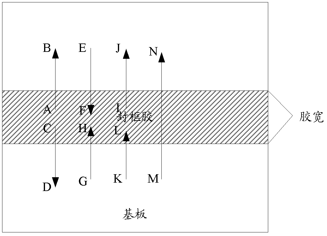
[0061] Step 3: Control the image device in the alignment detector to move along the line between the preset first scanning start point A and the first scanning end point B under the drive of the servo motor, such as Figure 2A As shown, and scan the brightness of each passing position during this movement; the selection of the starting point A and the ending point B should make the moving direction of the imaging device parallel to the direction of the glue width; According to the brightness scanning results of the imaging device during this movement, the data analysis device draws a graph as Figure 2B As shown in the curve, the abscissa of the curve is the coordinate value of each position point passed by the servo motor (ie, the image device) during the movement of the image device, and the coordinate value ...
Embodiment 2
[0066] Step 1: The glue applicator applies the sealant on the substrate;
[0067] Step 2: The thermal curing furnace cures the frame sealant coated on the substrate;
[0068] Step 3: Control the image device in the alignment detector to move along the line between the preset first scanning start point E and the first scanning end point F under the drive of the servo motor, such as Figure 2A As shown, and in the process of this movement, scan the brightness of each position point passed by; the selection of the starting point E and the ending point F should make the moving direction of the imaging device parallel to the direction of the glue width; According to the brightness scanning results of the imaging device during this movement, the data analysis device draws a graph as Figure 2B The curve shown; then, determine the brightness contrast peak in the curve drawn this time, and the position corresponding to the brightness contrast peak is an edge point position of the sea...
Embodiment 3
[0073] Step 1: The glue applicator applies the sealant on the substrate;
[0074] Step 2: The thermal curing furnace cures the frame sealant coated on the substrate;
[0075] Step 3: Control the image device in the alignment detector to move along the line between the preset first scanning starting point I and the first scanning ending point J under the drive of the servo motor, such as Figure 2A shown, and scan the brightness of each passing position during this movement; the selection of the starting point I and the ending point J should make the moving direction of the image device parallel to the direction of the glue width; According to the brightness scanning results of the imaging device during this movement, the data analysis device draws a graph as Figure 2B The curve shown; then, determine the brightness contrast peak in the curve drawn this time, and the position corresponding to the brightness contrast peak is an edge point position of the sealant;
[0076] Con...
PUM
 Abstract
Description
Claims
Application Information
PatSnap Eureka turns technology decisions into work you can execute. Powered by our Innovation Knowledge Graph, it runs expert workflows across engineering, life sciences, materials and intellectual property. Get your review-ready output in minutes.


