
Rapid locking coaxial connector

A technology of coaxial connectors and quick locks, applied in the direction of connections, parts of connection devices, coupling devices, etc., can solve the problems of low installation density, high manufacturing cost, low production efficiency, etc., and achieve anti-vibration and impact resistance Good, low manufacturing cost, easy installation

Active Publication Date: 2012-08-22
SHANGHAI AEROSPACE SCI & IND ELECTRIC APPLIANCE RES INST
View PDF9 Cites 21 Cited by
  • Summary
  • Abstract
  • Description
  • Claims
  • Application Information

AI Technical Summary

Problems solved by technology

However, with the development trend of product miniaturization, the installation space left for components is becoming more and more limited, and the threaded connection locking method exposes various disadvantages, such as installation and disassembly take a long time, and Requires minimum space between connectors for assembly tools, resulting in low mounting density
[0004] In view of the problems existing in the above-mentioned prior art, those skilled in the art have developed coaxial connectors with various quick-lock structures according to the requirements for quick-installation of coaxial connectors, such as patent EP1337008A2 and patent EP1222717A1. These quick-lock structures The characteristics are: the movable locking part is set on the plug end, and its internal structure is relatively complicated, and special tooling is required to ensure the quality, high processing accuracy requirements, and low production efficiency. Due to high manufacturing costs, this product has seriously affected the civilian field. the widespread use of

Method used


Image

  • Rapid locking coaxial connector
  • Rapid locking coaxial connector
  • Rapid locking coaxial connector

Examples


Embodiment Construction

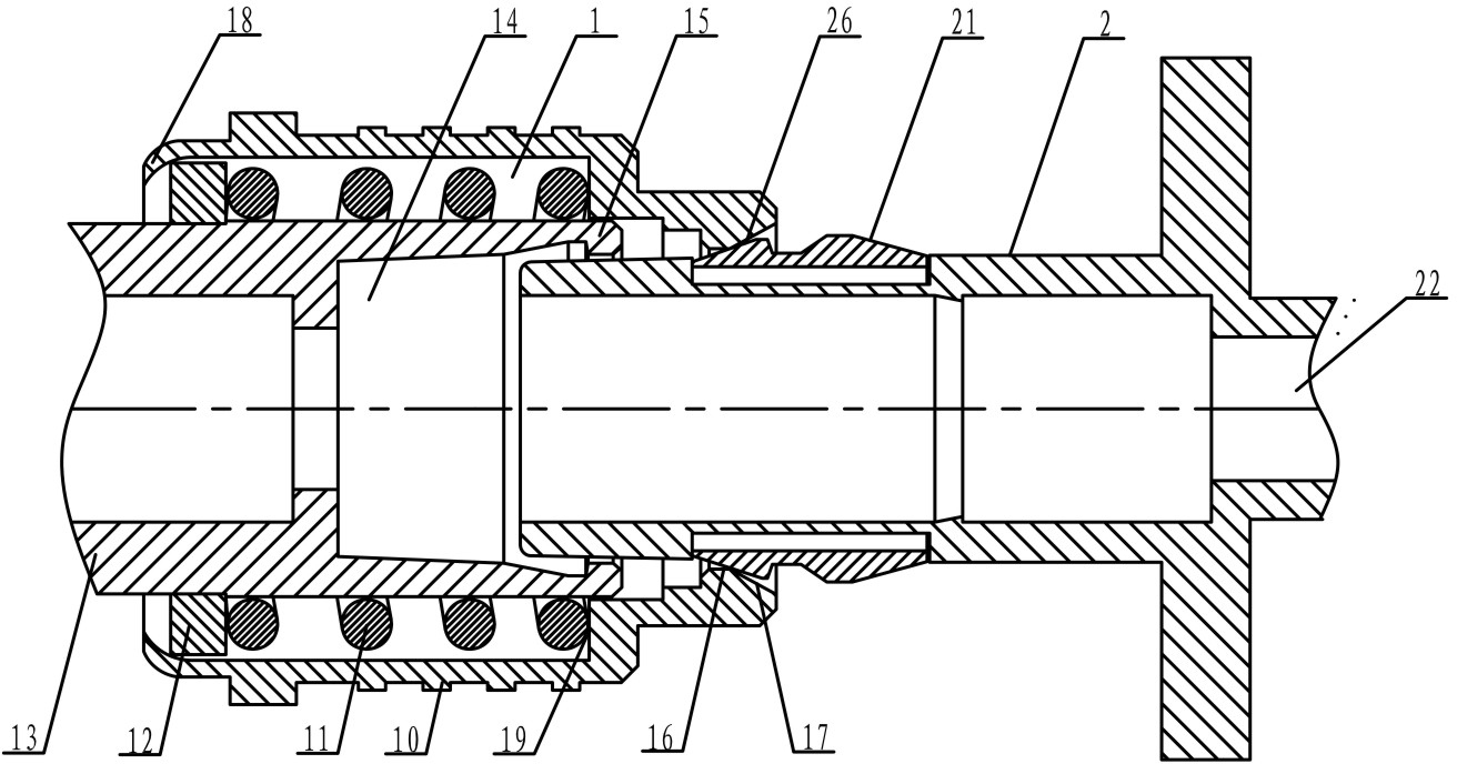
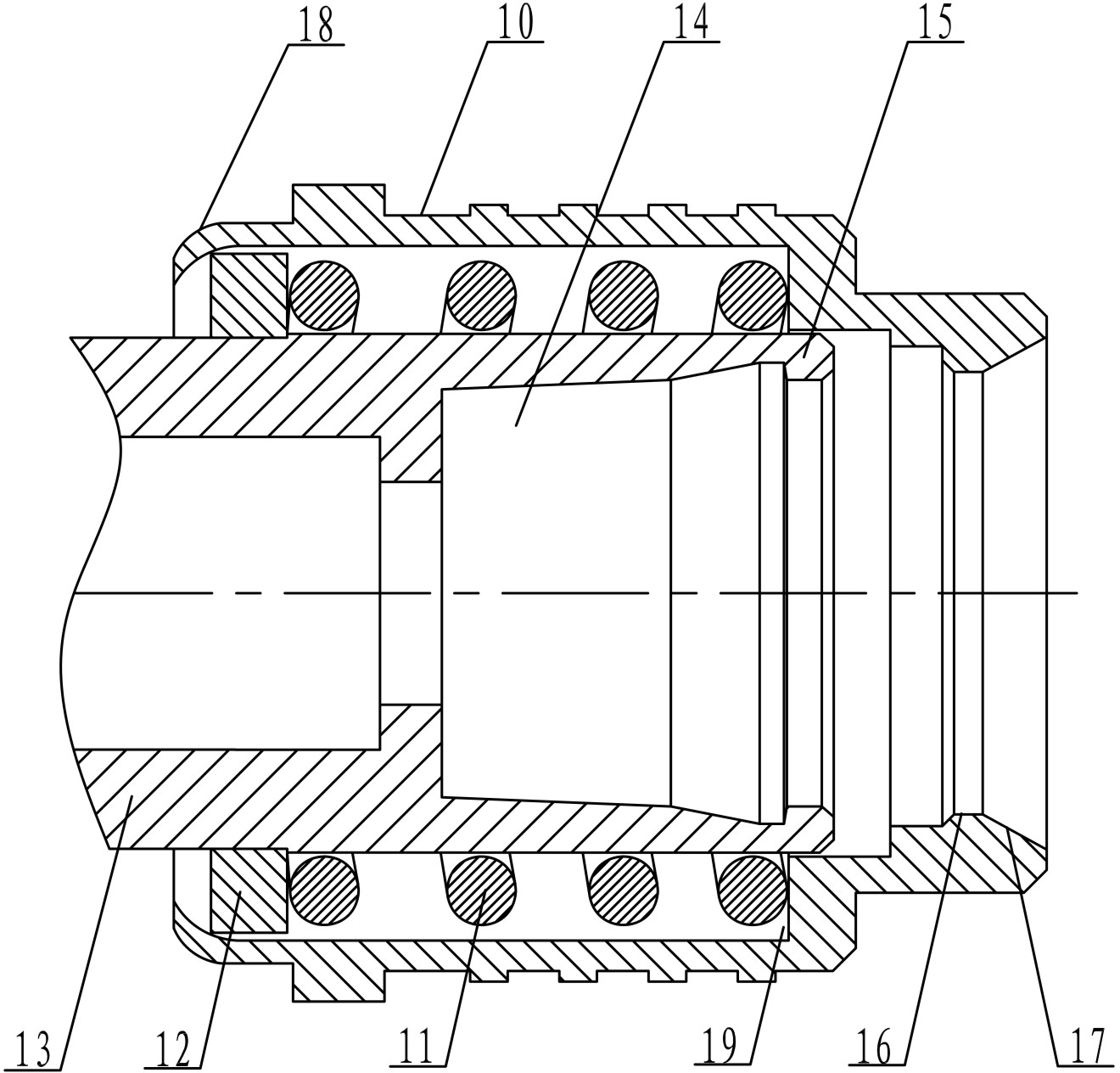
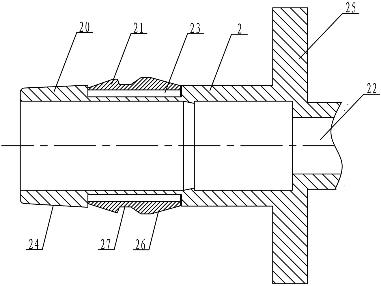
[0016] See attached figure 1 , the present invention is composed of a plug 1 and a socket 2. The plug 1 is assembled with a screw sleeve 10 after the outer conductor 13 is fitted with a spring 11 and a pressure-fit retaining ring 12. The outer conductor 13 is provided with claws 15 and socket holes 14. The connector, the claw 15 is set at the port of the socket hole 14; the socket 2 is composed of a clasp ring 21 set on the shell 20, and the clasp ring 21 is an elastic sleeve provided with a guide slope 26, a clamping groove 27 and an axially cut groove 28 The card slot 27 is a trapezoidal slot with slopes 29 on both sides; the docking of the plug 1 and the socket 2 is firstly that the guide slope 17 on the screw sleeve 10 contacts the front guide slope 26 on the collar 21. This process makes the card While the ring 21 is radially centered, the compression collar 21 radially shrinks to a diameter smaller than the inner diameter of the insertion hole 14, and the claw 15 enters ...


PUM


Abstract

The invention discloses a rapid locking coaxial connector, which comprises a plug and a socket and is characterized in that the plug is formed by assembling a screw sleeve with an outer conductor which is sleeved by springs and pressing retaining rings, and the outer conductor of the plug is a connection piece provided with a clamping jaw and a plug-in hole; one end of the screw sleeve is provided with a guiding oblique plane and an unlock plane, the other end of the screw sleeve is provided with a sleeve which has a bending structure; the socket is composed of an outer casing and a clamping ring, and the clamping ring is an elastic sleeve ring which is provided with guiding slopes, a clamping groove and an axial cutting groove and is sleeved on the outer casing to be in clamping connection with a groove; and the plug and the socket are connected in an inserting mode, and the clamping jaw enters into the clamping groove by means of an axial thrust and is locked in the clamping groove by means of the springs, so that rapid connection and locking between the plug and the socket are achieved. Compared with coaxial connectors in prior art, the rapid locking coaxial connector is simple in structure, rapid and convenient in butting locking and disassembling, reliable in connection, good in vibration resistance and impact resistance, convenient to install and low in production cost.

Description

technical field [0001] The invention relates to the technical field of electric component plugging, in particular to a quick-lock coaxial connector suitable for a new type of interface. Background technique [0002] In today's electronic communication fields, such as voice transmission, data transmission, image transmission, etc., the required signal propagation speed is getting faster and higher, and the frequency is getting higher and higher. At the same time, the degree of systematization and integration is getting higher and higher. The application of the corresponding electric connector is also more and more extensive. The coaxial connector realizes the conduction and separation of the transmission path through the elastic connection and separation of the contacts. The connection and locking reliability of the coaxial connector directly affects the performance of the entire system. It has a great influence on the reliability and reliability of the connector. The suitab...

Claims


Application Information

Patent Timeline
IPC IPC(8): H01R13/627
Inventor 曹永泉周靖波
Owner SHANGHAI AEROSPACE SCI & IND ELECTRIC APPLIANCE RES INST
Learn More