Power factor regulating circuit and regulating method

A power factor adjustment and circuit technology, applied in the direction of reactive power adjustment/elimination/compensation, reactive power compensation, etc., to achieve the effect of small control range, simple control circuit, and reduced switching loss

Inactive Publication Date: 2012-08-22
SOUTH CHINA UNIV OF TECH
View PDF6 Cites 11 Cited by
  • Summary
  • Abstract
  • Description
  • Claims
  • Application Information

AI Technical Summary

Problems solved by technology

The invention not only solves the problem of capacitance withstand voltage, but also can realize power factor regulation well by changing the control program for different loads

Method used


Image

  • Power factor regulating circuit and regulating method
  • Power factor regulating circuit and regulating method
  • Power factor regulating circuit and regulating method

Examples


Embodiment Construction

[0016] The specific embodiments of the present invention will be further described below in conjunction with the accompanying drawings, but the implementation and protection scope of the present invention are not limited thereto.

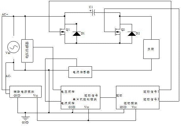
[0017] figure 1 The overall structure diagram of the power factor adjustment circuit of the example of the present invention is given, which includes a main circuit, an auxiliary power supply module, a single-chip microcomputer control module, and a drive module. The main circuit includes a first switch tube Q1, a second switch tube Q2, a first diode D1, a second diode D2, a first capacitor C1, a load, a voltage sensor, and a current sensor. The first switching tube is connected in antiparallel to the first diode, the second switching tube is connected in antiparallel to the second diode, the source of the first switching tube is connected in series with the source of the second switching tube to form a bridge arm, and the first capacitor and the br...


PUM


Abstract

The invention discloses a power factor regulating circuit and a regulating method. The regulating circuit comprises a main circuit, an auxiliary power supply module, a singlechip control module and a driving module. An input power source Vac is connected with the input end of the auxiliary power supply module; the output end of the auxiliary power supply module is respectively connected with the singlechip control module and the power source input end of the driving module; the singlechip control module samples the input voltage and the input current of the main circuit; the input end of the driving module is connected with the driving signal end of the singlechip control module; and the output end of the driving module is connected with two switch tubes of the main circuit. With the regulating method, automatic regulation to different loads can be realized, and the power factor regulating circuit and the regulating method are mainly used for reactive power compensation for perceptual power loads such as a transformer, an electric motor, a fluorescent lamp and an electric-arc furnace in a power grid. According to the invention, through the regulation of the power factor, the load can be unimpeded and the load voltage and the load current can be of the same phase.

Description

technical field [0001] The invention relates to a power factor adjustment technology, in particular to a power factor adjustment circuit and an adjustment method for reactive power compensation of inductive power loads in a power grid such as transformers, motors, fluorescent lamps and electric arc furnaces. Background technique [0002] At present, reactive power compensation can be divided into high-voltage reactive power compensation and low-voltage reactive power compensation. The characteristic of reactive power compensation is that it only compensates the front, so installing a reactive power compensation device at high voltage is expensive, and the compensation effect is not obvious. The methods of low-voltage reactive power compensation can be divided into centralized compensation and local compensation. Reactive power compensation devices can be divided into static, dynamic, static + dynamic. The complete set of low-voltage reactive power automatic compensation de...

Claims


Application Information

Patent Timeline
Patent Type & Authority Applications(China)
IPC IPC(8): H02J3/18
CPCY02E40/30
Inventor 康龙云姜凯林玉健温懋勤易伯瑜
Owner SOUTH CHINA UNIV OF TECH
Why Eureka
Try Eureka