Work system

A working system and working technology, applied in manufacturing tools, metal processing equipment, manipulators, etc., can solve the problems of equipment cost increase and achieve the effect of suppressing equipment cost

Inactive Publication Date: 2012-08-29
YASKAWA DENKI KK
View PDF8 Cites 7 Cited by
  • Summary
  • Abstract
  • Description
  • Claims
  • Application Information

AI Technical Summary

Problems solved by technology

[0004] However, when conveying workpieces using conveying devices such as

Method used


Image

  • Work system
  • Work system
  • Work system

Examples


Example Embodiment

[0021] Hereinafter, embodiments of the working system disclosed in the present application will be explained in detail with reference to the drawings. The present invention is not limited to the following embodiments.
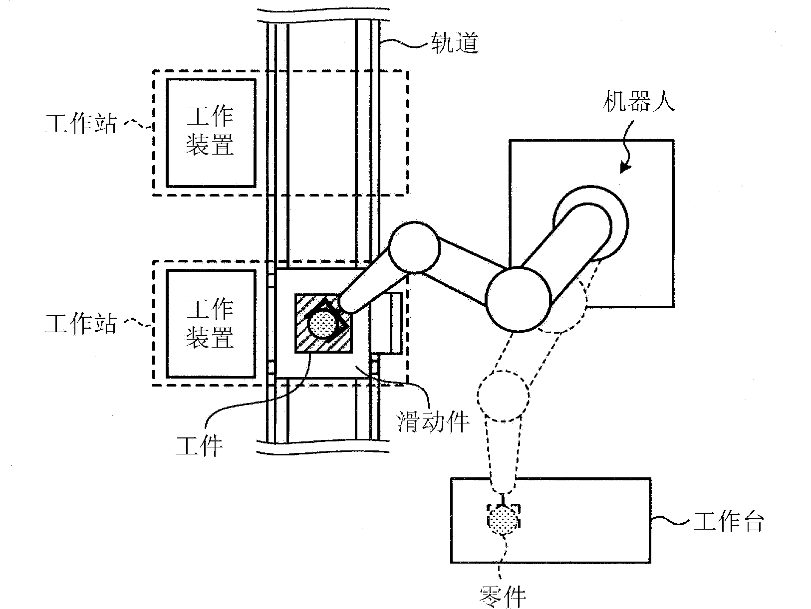
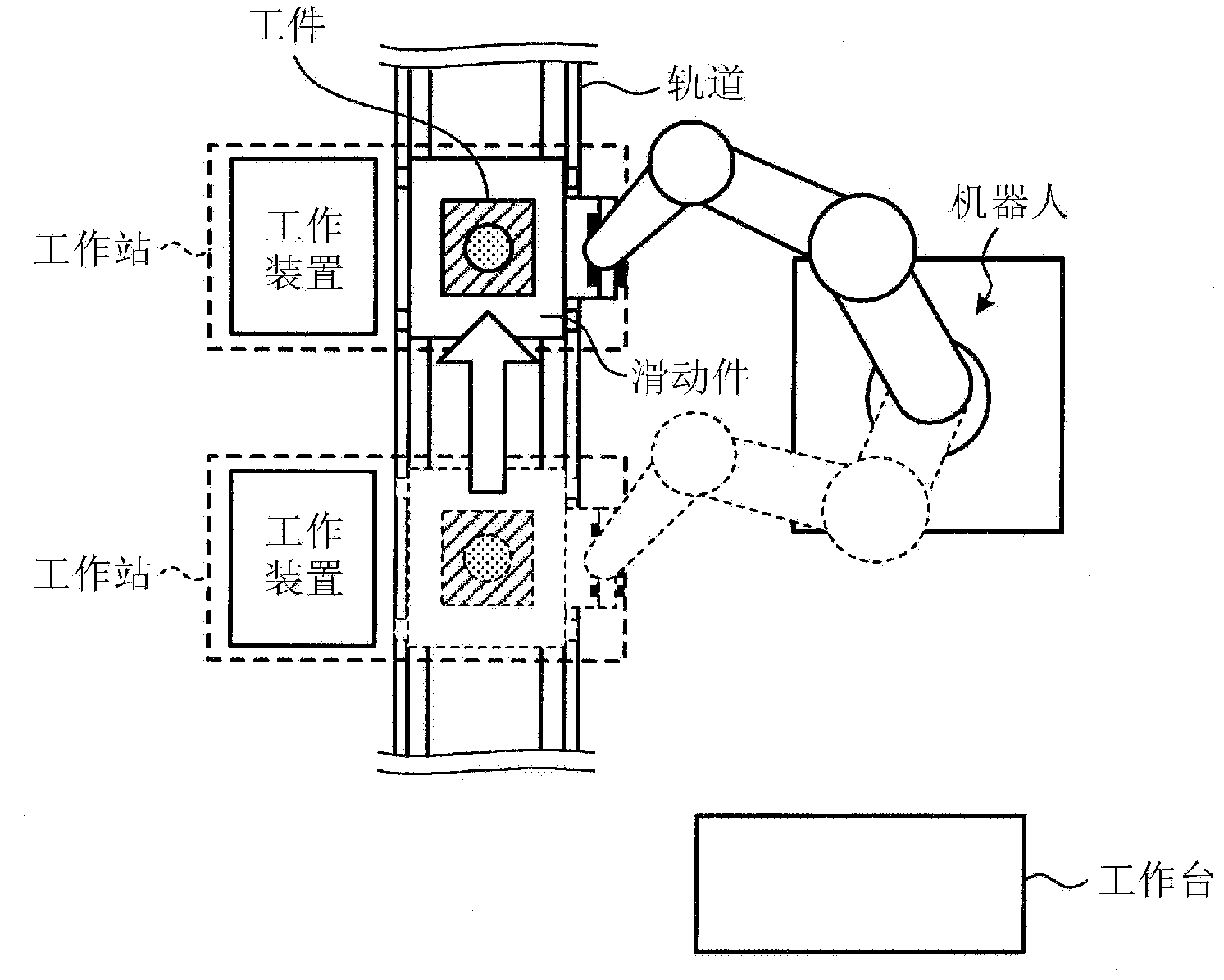
[0022] First, refer to Figure 1A with Figure 1B The outline of the working system according to the first embodiment will be briefly explained. Figure 1A with Figure 1B It is a schematic explanatory diagram of the working system according to the first embodiment. Such as Figure 1A with Figure 1B As shown, the work system according to the first embodiment is a system that automatically performs a predetermined work on a workpiece as a work target by using a robot or the like.

[0023] Specifically, the working system according to the first embodiment includes a robot and a plurality of workstations. The robot is, for example, a single-arm industrial robot. The workstation is a place where a predetermined work is performed on the workpiece.

[0024] For example, su...


PUM


Abstract

A work system according to embodiments includes a robot and work stations. The robot performs a predetermined work on a workpiece, as a work target. The work stations are places where the predetermined work is performed on the workpiece. The robot performs conveying of the workpiece between the work stations.

Description

technical field [0001] The embodiments discussed herein relate to a working system. Background technique [0002] Conventionally, there is known a work system that automatically performs work performed manually, such as assembly work and machining work, by using an industrial robot or the like. [0003] In this type of work system, generally, while a workpiece as a work target is conveyed by a conveying device such as a belt conveyor, predetermined work (e.g., , see Japanese Patent Laid-Open No. 2010-162652). [0004] However, when workpieces are conveyed using a conveyor such as a belt conveyor as in a conventional work system, equipment costs increase. [0005] The technology discussed herein is achieved in view of the above-mentioned problems, and an object of the present invention is to provide an operating system capable of suppressing equipment costs. Contents of the invention [0006] A working system according to an aspect of an embodiment includes a robot and a...

Claims


Application Information

Patent Timeline
IPC IPC(8): B25J13/00
CPCB25J9/0093B23P21/004B25J9/0096Y10S901/16
Inventor 堤亮介村上宏彰永野义久
Owner YASKAWA DENKI KK
Why Eureka
Try Eureka