Joint control device and method for low waterhead Kaplan turbine

It is a synergistic regulation and paddle-rotating technology, which can be used in safety devices, mechanical equipment, hydropower, etc., and can solve the problems of reduced guide vane opening, reduced downtime and transition time, and reduced unit stability.

Active Publication Date: 2014-06-04
POWERCHINA XIBEI ENG
View PDF7 Cites 0 Cited by
  • Summary
  • Abstract
  • Description
  • Claims
  • Application Information

AI Technical Summary

Problems solved by technology

This adjustment is well known, but there are two problems. It is correct to improve the efficiency of the turbine and obtain the maximum energy during normal operation and start-up. However, it is correct when the turbine is shut down or transitioned from power generation to phase modulation. The hydraulic turbine has a transition period from the working condition of the turbine to the working condition of the reverse pump and the phase modulation and compression. At this time, this adjustment: 1. During the period of shutdown or transition from power generation to phase modulation (phase modulation and compression), the turbine has In the working condition of the reverse water pump, in this case, the decrease of the opening of the guide vane, the decrease of the flow rate of the unit, and the decrease of the angle of the runner blades are the increase of the head of the reverse water pump, which becomes the cause of the shutdown of the vertical unit and the lifting of the machine during the transition process. The main factors, such as Gezhou generator set shut down and lift, and the Syrian Dishlin power station unit designed by our institute is lifted during the process of phase modulation and compression; increase the axial rear thrust of the horizontal generator set
Decrease the stability of the unit
2. At this time, the unit does not need to obtain a lot of water energy and needs to stop quickly or the transition process is completed quickly. According to the above adjustment, the movable guide vanes of the water turbine are all closed to 0 opening, and the runner blades will be reduced to the minimum angle position. Small, the turbine can get the maximum water energy in the process, which is not conducive to the reduction of downtime and transition time

Method used


Image

  • Joint control device and method for low waterhead Kaplan turbine
  • Joint control device and method for low waterhead Kaplan turbine

Examples


Embodiment Construction

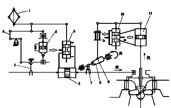
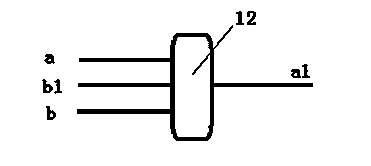
[0018] Such as figure 1 , 2 As shown in the figure, a low-head rotary paddle turbine association regulating device, the oil supply pipe a of the vane pressure distribution valve 10 is connected to the oil supply oil circuit a1 through the two-way connection of the four-way reversing valve 12, and the oil supply pipe a of the vane pressure distribution valve 10 The oil return pipe b and the oil return circuit b1 are connected through the other two ports of the four-way reversing valve 12. Controlling the valve plate of the four-way reversing valve 12 can make the oil supply pipe a of the vane pressure distribution valve 10 and the oil return circuit b1 two-way. The oil return pipe b is in two-way communication with the oil supply oil passage a1, and the four-way reversing valve 12 can also be controlled so that the oil supply pipe a of the vane pressure distribution valve 10 is in two-way communication with the oil supply oil passage a1, and the vane pressure distribution The ...


PUM


Abstract

The invention belongs to hydraulic mechanical engineering, and particularly relates to a joint control device and method for a low waterhead Kaplan turbine. The device at least comprises a blade distributing valve (10) which is connected with a joint mechanism, wherein two ways of a four-way valve (12) are connected between an oil supply pipe of the blade distributing valve (10) and an oil supply line, and the other two ways of the four-way valve (12) are connected between an oil return pipe of the blade distributing valve (10) and an oil return line. The device and the method provided by the invention can let the turbine to obtain stable performance during the process of shutting down or shifting from a power generation working condition to a phase modulation working condition, and is beneficial to reducing the time for shutting down and transition.

Description

technical field [0001] The invention belongs to hydraulic mechanical engineering, in particular to a low-head swirling paddle turbine associated regulating device and method. Background technique [0002] The regulation system of the low-head rotary paddle turbine is double regulation, that is, the movable guide vane of the turbine is linked with the runner blade. It has been proved by experiments and practice that the low-head turbine adopts double regulation, which can enable the turbine to obtain a wider high-efficiency area, improve the overall efficiency of the turbine, maximize the use of water energy, and obtain the maximum kinetic energy. The double adjustment is adjusted in this way: with the increase of the output of the unit, the opening of the movable guide vane increases, the application flow of the turbine increases, the angle of the runner blade increases, and the output of the unit decreases; vice versa; when the unit stops, the opening of the movable guide v...

Claims


Application Information

Patent Timeline
Patent Type & Authority Patents(China)
IPC IPC(8): F03B15/12F03B15/06
CPCY02E10/226Y02E10/20
Inventor 王耀洲
Owner POWERCHINA XIBEI ENG
Why Eureka
Try Eureka