Liquefied natural gas filling pry

A technology of liquefied natural gas and liquid level, which is applied in the direction of gas/liquid distribution and storage, equipment loaded into pressure vessels, pipeline systems, etc., which can solve the problems of inability to establish LNG gasification stations, inability to pay fees in time, and inability to realize remote monitoring To achieve the effect of remote monitoring, excellent evaporation rate index and stable pressure

Inactive Publication Date: 2012-08-29
ZHANGJIAGANG HANJUNG CIT CO LTD
View PDF6 Cites 16 Cited by
  • Summary
  • Abstract
  • Description
  • Claims
  • Application Information

AI Technical Summary

Problems solved by technology

[0002] As an efficient and clean fuel, liquefied natural gas (usually referred to as LNG) has formed a large-scale industry when it is used in daily life instead of coal gas. The current LNG fueling skid includes storage tanks. The output port is connected with a gas supply pipeline for supplying gas to the user terminal. The gas supply pipeline is provided with a vaporizer and a metering control system in sequence along the natural gas flow direction. The storage tank is provided with an input port and an exhaust port. The exhaust port is connected to the pressure regulating pipeline system. The pressure regulating pipeline system includes a booster for increasing the pressure in the storage tank. Although the storage tank is now equipped with a liquid level detection device and a pressure detection device device, but requires staff to monitor the operation all the time, and cannot realize remote monitoring, which is very inconvenient for practical application
[0003] At present, LNG is used first and then charged. Some users do not cooperate during the charging process, and various problems often occur, resulting in the fee not being credited in time, which has become an extremely headache for the LNG industry.
[0004] In addition, the LNG gas supply system is currently only limited to the construction of gas filling stations, and the cost is relatively high. For the situation of small gas consumption, such as far away from the city and the pipeline network, it is impossible to establish an LNG gasification station or there is no need to establish a small LNG gasification station. Residential areas, etc., there are great limitations in use

Method used


Image

  • Liquefied natural gas filling pry
  • Liquefied natural gas filling pry

Examples


Embodiment Construction

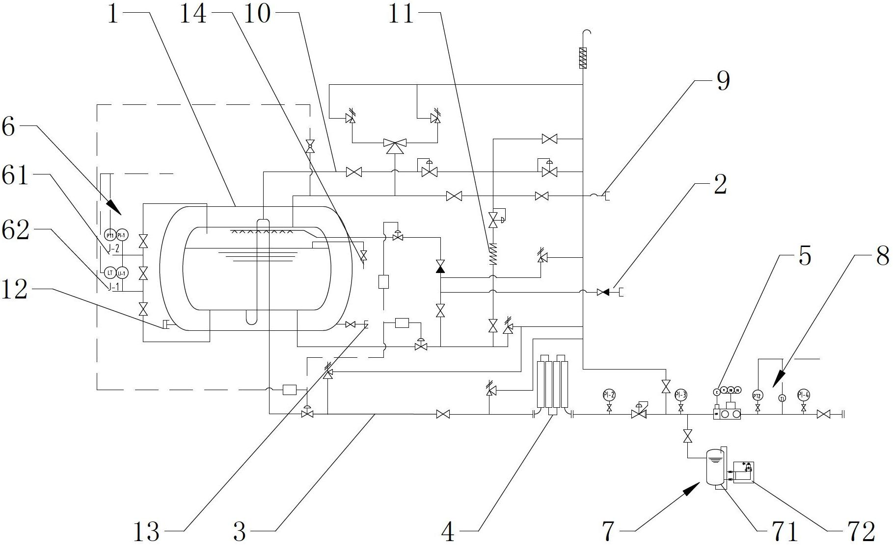
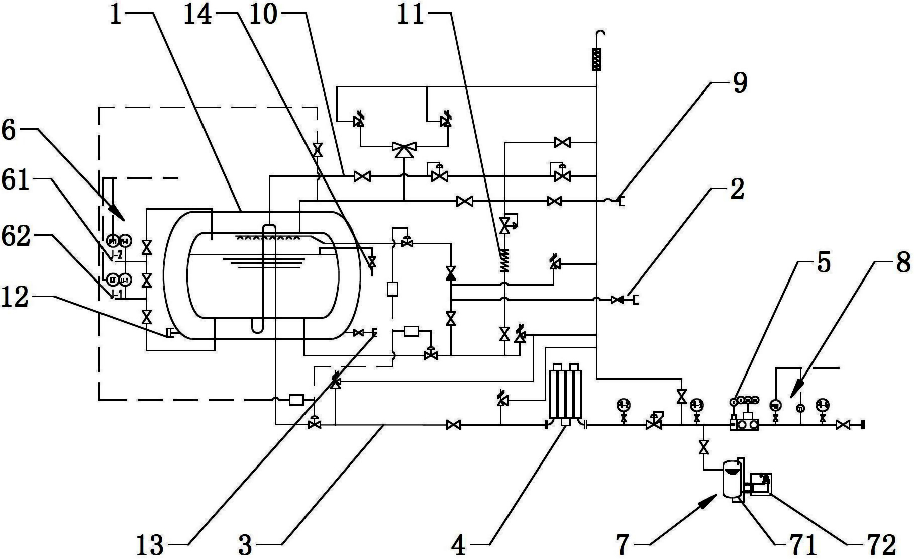
[0029] The present invention will be described in further detail below through specific examples.

[0030] Such as figure 1 As shown, the liquefied natural gas refueling skid includes a storage tank 1, the storage tank 1 includes an inner tank body and an outer tank body, and a heat-insulating and radiation-proof heat-insulating material is provided in the cavity between the inner tank body and the outer tank body, and the cavity It is connected with the vacuum port 12, and the outer tank body is provided with a vacuum test port 13 communicating with the cavity. The storage tank 1 is provided with an overflow pipeline 14, and the overflow pipeline 14 is provided with an overflow valve. The storage tank 1 is provided with an input port and an exhaust port, the input port is connected to the liquid filling pipeline 2, and the exhaust port is connected to the pressure regulating pipeline system. The pressure regulating system includes a supercharger 11 and the exhaust port of th...


PUM


Abstract

The invention discloses a liquefied natural gas filling pry, which comprises a storage tank, wherein an output opening is arranged at the bottom of the storage tank and is connected with a gas supply pipeline, a carburetor and a metering control system are sequentially arranged on the gas supply pipeline in the flow direction of natural gas, an input opening and a gas discharge opening are arranged on the storage tank, the input opening is connected with a liquid filling pipeline, the gas discharging opening is connected with a pressure regulating pipeline system, the metering control system comprises a turbine flowmeter with an integrated circuit (IC) card, the carburetor and the turbine flowmeter with the IC card are sequentially arranged on the gas supply pipeline in the output direction of the natural gas, finally, a user terminal is reached, and a liquid level pressure detection system is connected onto the storage tank. When users need to use the gas, only the card punching of the IC card is needed. The gas supply pipeline is opened when money is saved in the IC card. The gas supply pipeline cannot be opened when no money is saved in the IC card. The automatic gas supply is perfectly realized in the region. The liquid level pressure detection system is arranged on the storage tank, the real-time monitoring can be realized on the storage tank in remote distance, and the inconvenience caused by manual in-site monitoring is avoided.

Description

technical field [0001] The invention relates to a liquefied natural gas supply device, in particular to a liquefied natural gas filling skid. Background technique [0002] As an efficient and clean fuel, liquefied natural gas (usually referred to as LNG) has formed a large-scale industry when it is used in daily life instead of coal gas. The current LNG fueling skid includes storage tanks. The output port is connected with a gas supply pipeline for supplying gas to the user terminal. The gas supply pipeline is provided with a vaporizer and a metering control system in sequence along the natural gas flow direction. The storage tank is provided with an input port and an exhaust port. The exhaust port is connected to the pressure regulating pipeline system. The pressure regulating pipeline system includes a booster for increasing the pressure in the storage tank. Although the storage tank is now equipped with a liquid level detection device and a pressure detection device devi...

Claims


Application Information

Patent Timeline
Patent Type & Authority Applications(China)
IPC IPC(8): F17C5/02F17C13/02F17C13/00F17D1/02F17D3/01F17D3/18
Inventor 高卫
Owner ZHANGJIAGANG HANJUNG CIT CO LTD
Why Eureka
Try Eureka