Control system and control method of dancer roll

A pneumatic control system and control method technology, applied in the direction of control/adjustment system, non-electric variable control, and simultaneous control of multiple variables, etc., can solve problems such as broken furnace belt, strip steel broken, accidents, etc., and reduce labor intensity Effect

Active Publication Date: 2014-03-05
BAOSHAN IRON & STEEL CO LTD
View PDF1 Cites 0 Cited by
  • Summary
  • Abstract
  • Description
  • Claims
  • Application Information

AI Technical Summary

Problems solved by technology

This control method increases the labor intensity of the operator, especially when the operator forgets to pull out the fixing pin of the jumping roller, it is easy to cause an accident of broken belt of the furnace, and the operation reliability of the unit is poor;
[0006] 3. Due to the unique zinc pot process equipment of the hot-dip galvanizing unit, the strip steel is soaked in the zinc pot during the operation of the unit. If it is not jogged at regular intervals, the strip steel will break and cause an accident.

Method used


Image

  • Control system and control method of dancer roll
  • Control system and control method of dancer roll
  • Control system and control method of dancer roll

Examples


Embodiment Construction

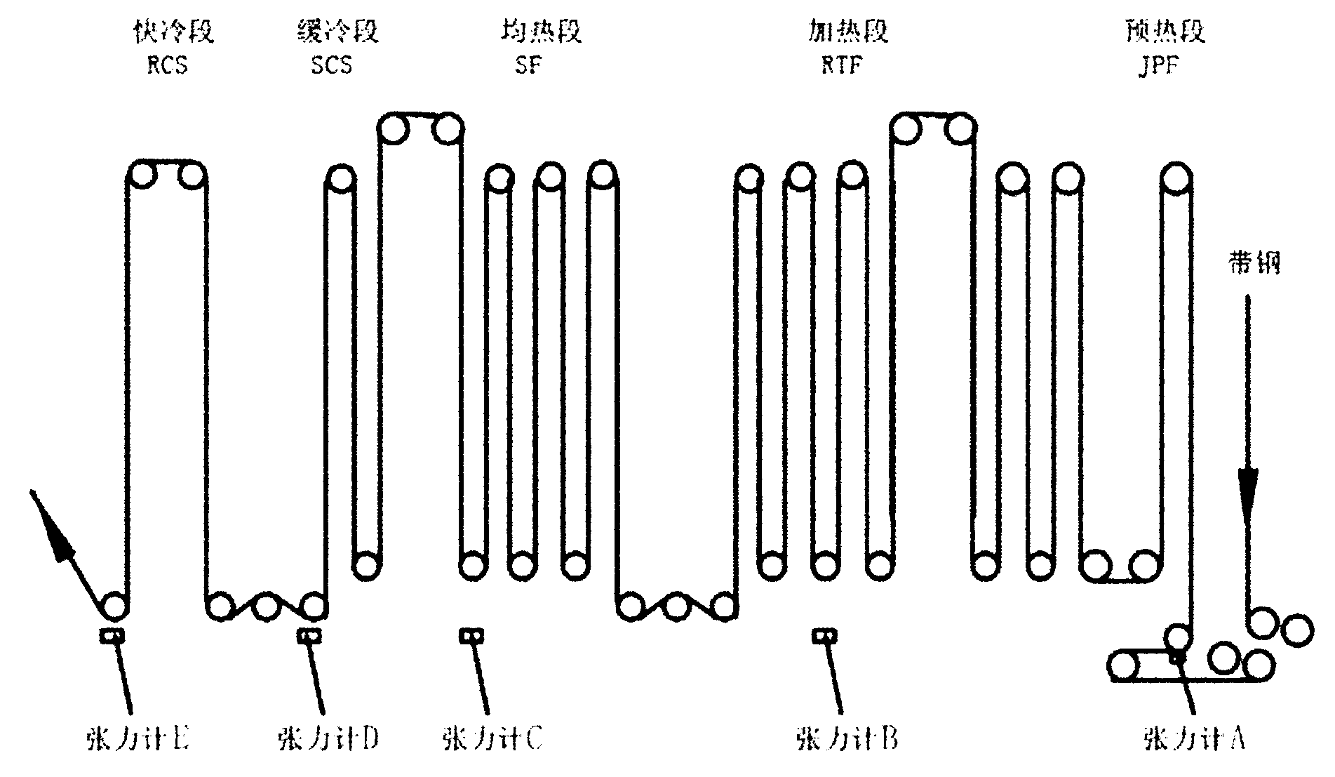
[0062] Such as figure 1 As shown, the equipment in the furnace section of the hot-dip galvanizing unit, the strip passes through the preheating section (JPF), heating section (RTF), soaking section (SF), slow cooling section (SCS), rapid cooling section (RCS) and other equipment , Each section is provided with a corresponding tensiometer A to a tensiometer E for tension testing.

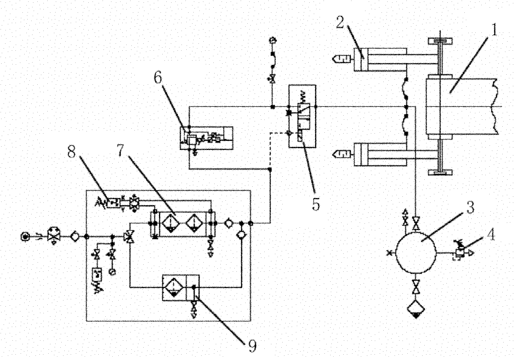
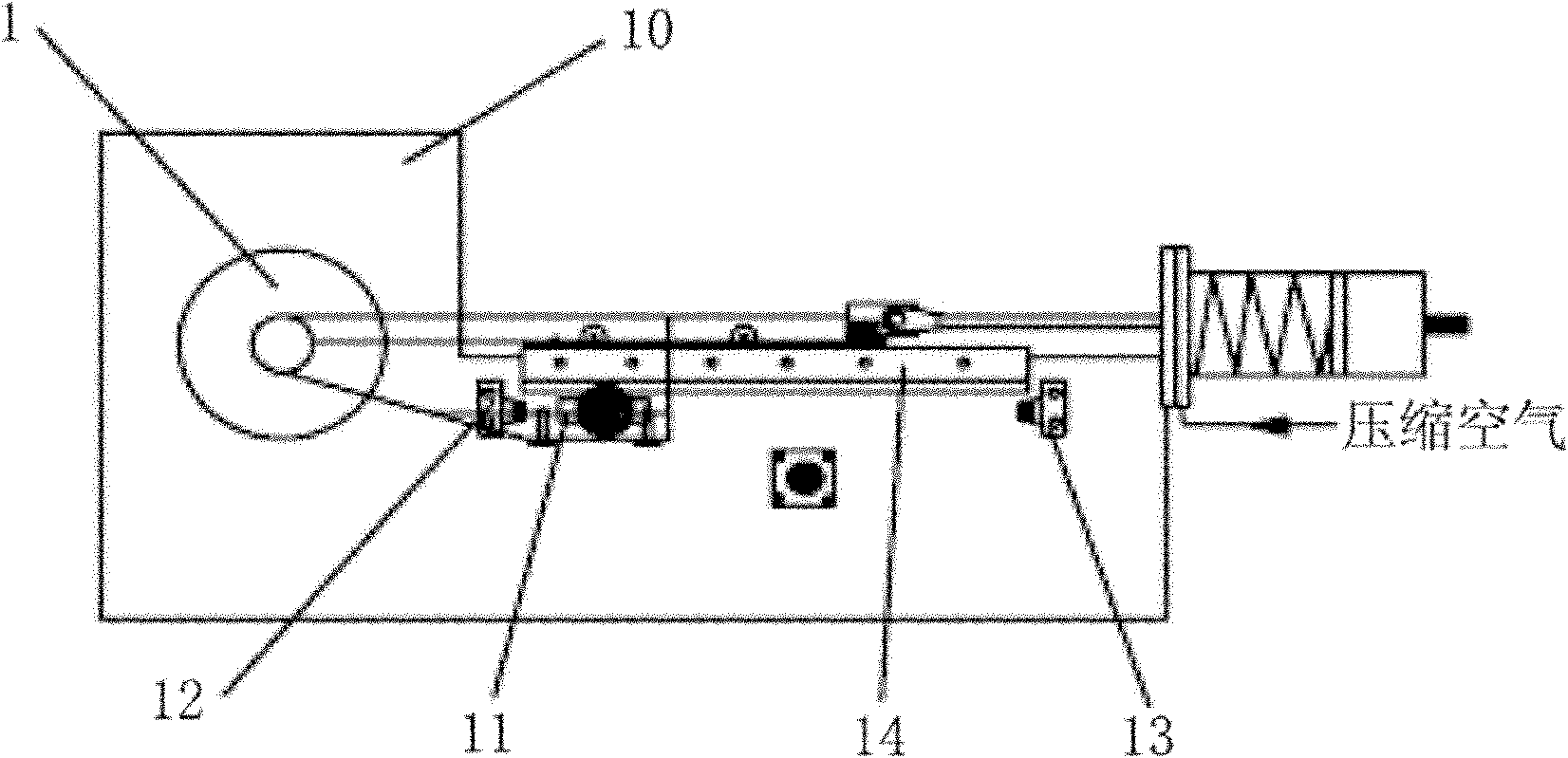
[0063] Aiming at the problems existing in the actual application of the prior art, this dancing roller control system is proposed, such as figure 2 and image 3 As shown, the dancing roller 1 is installed on a fixed frame 10, and a movable frame is installed on two high-precision rails 14 (the movable frame and the fixed frame 10 are different frames here), and four guide rails are installed. A low inertia dancer roller 1 is supported on this frame of the wheel. The control of the jumping roller adopts a control mode combining tension control as the main and position control as the slave. The co...


PUM


Abstract

The invention relates to a control system and a control method of a dancer roll, wherein the control system comprises a guide rail, a position sensor and a pneumatic control system; a movable frame used for bearing the dancer roll is arranged on the guide rail; the position sensor is used for detecting the stroke variation between a target position and an initial position of the dancer roll; the pneumatic control system is used for providing tensile force to shift the dancer roll to the target position; and the pneumatic control system at least comprises a pneumatic proportional valve. The control method comprises a step of controlling the tensile force of the dancer roll and a step of controlling the position of the dancer roll, wherein the step of controlling the tensile force comprises the following steps of: a, calculating a pressure set value of the dancer roll, and b, converting the pressure set value of the dancer roll into a pressure set value of the pneumatic proportional valve; and the step of controlling the position also comprises the following steps of: a, recognizing the position of the dancer roll, and b, converting the difference value between a position set value and an actual value of the dancer roll into a speed compensation value of a unit idler roller.

Description

technical field [0001] The present invention relates to a control technology and application of jumping rolls in a continuous processing production line, specifically a control system for jumping rolls and a control method using the system in the application field of equipment control technology for hot-dip galvanizing units in the cold rolling industry . Background technique [0002] The equipment in the furnace section of the hot-dip galvanizing unit includes tensioning rolls, jumping rolls, preheating section (JPF), heating section (RTF), soaking section (SF), slow cooling section (SCS), rapid cooling section (RCS) and hot-dip galvanizing section. Tension rollers and other equipment, an important indicator of furnace section equipment is that the tension must be controlled within a certain range of requirements, among which the guaranteed value of tension control in the preheating section (JPF) of the furnace section of the hot-dip galvanizing unit is: at steady state Th...

Claims


Application Information

Patent Timeline
Patent Type & Authority Patents(China)
IPC IPC(8): G05D27/02
Inventor 龚建平高玉强潘维平
Owner BAOSHAN IRON & STEEL CO LTD
Why Eureka
Try Eureka