Carpet cleaner

A technology for cleaners and carpets, used in carpet sweepers, carpet cleaning, cleaning equipment, etc., can solve the problems of insufficient inhalation of dust or moisture, reduced cleaning efficiency, and increased space occupied, to prevent suction, prevent Short circuit, easy to fall off effect

Inactive Publication Date: 2012-09-05
SUZHOU HAAN TECH +1
View PDF6 Cites 6 Cited by
  • Summary
  • Abstract
  • Description
  • Claims
  • Application Information

AI Technical Summary

Problems solved by technology

However, if it is to spray uniformly to the agitator 12, it is necessary to increase the pumping capacity of the pump 14, thereby causing an increase in occupied space and a high price, which is not economical at this level. The nozzle pipe form sprays the cleaning liquid near the center of the length

Method used


Image

  • Carpet cleaner
  • Carpet cleaner
  • Carpet cleaner

Examples


Embodiment Construction

[0090] Hereinafter, preferred embodiments of the present invention will be described with reference to the drawings.

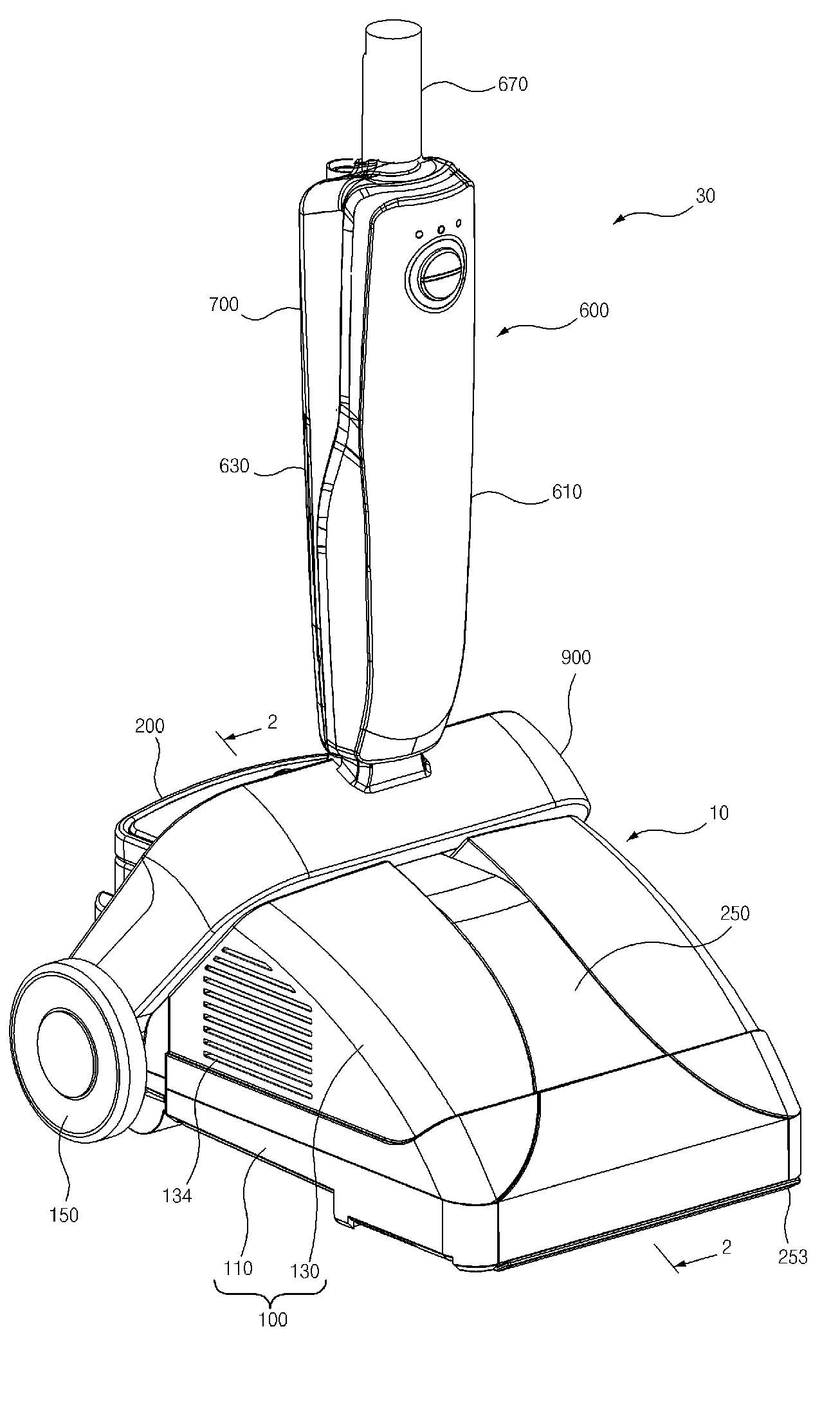
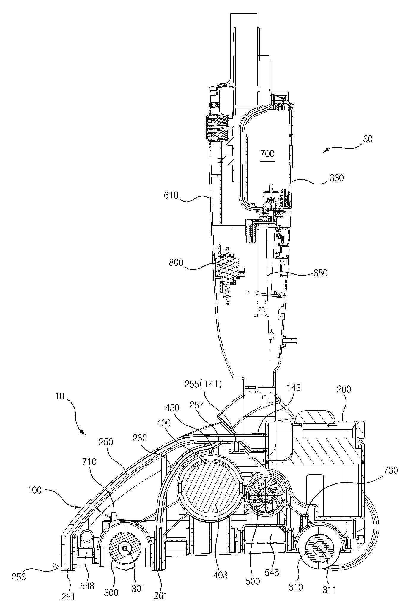
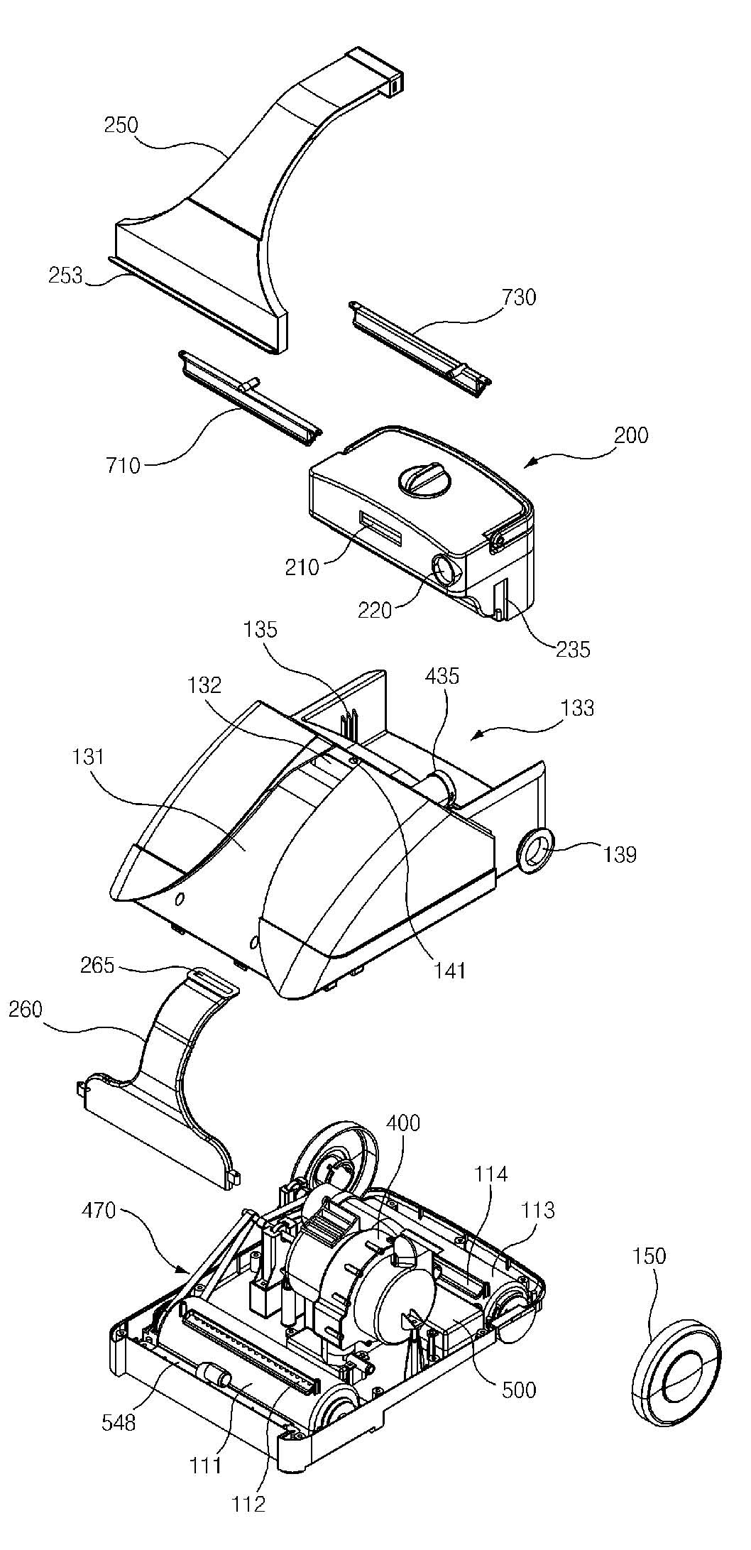
[0091] figure 1 It is a perspective view of the appearance of the carpet cleaner involved in the preferred embodiment of the present invention, figure 2 for along figure 1 The sectional view seen after the 2-2 line is cut, image 3 and Figure 4 for figure 1 Combination and separation perspective view of the base components, Figure 5 and Image 6 to remove image 3 Left and right perspective view of the state after the upper case, Figure 7 for from Figure 5 A perspective view of the state after removing the suction duct, Figure 8 for Image 6 bottom perspective view of Figure 9 to remove Figure 8 A perspective view of the state behind the base, Figure 10 A three-dimensional view of the dryer, Figure 11 for along Figure 10 The sectional view seen after the 11-11 line is cut, Figure 12 is a side view of the shape of the suction moto...


PUM


Abstract

The invention relates to a carpet cleaner, which is characterized in that, a wet carpet can be rapidly dried, and washing efficiency can be improved via sufficient dissolution of a lotion, and particularly relates to a carpet cleaner which realizes stabilization of a heater via air supply to the heater through drive force of a sucking motor.

Description

technical field [0001] The present invention relates to a carpet cleaner that can not only quickly dry wet carpets, but also improve washing efficiency by fully dissolving lotion liquid, especially relates to utilizing the driving force of a suction motor to supply air to a heater to stabilize the heater A modernized carpet cleaner. Background technique [0002] As a conventional carpet cleaner, a technique disclosed in patent documents has been proposed. [0003] Such as Figure 16 As shown, the existing carpet cleaner has: a handle body 1 disposed along the up and down direction; A pair of moving wheels 9 are combined at a certain interval; a water supply cylinder 4 is arranged on the front upper side of the handle body 1 and stores a cleaning liquid 3 mixed with lotion and lotion; and a water collection cylinder 7. The water collecting cylinder 7 is arranged on the lower side of the water supply cylinder 4, and is used for collecting the sewage 6 sucked in the cleaning ...

Claims


Application Information

Patent Timeline
IPC IPC(8): A47L11/32A47L11/34A47L11/40
CPCA47L11/34A47L11/4016A47L11/4044A47L11/4094
Inventor 韩京姬
Owner SUZHOU HAAN TECH
Why Eureka
Try Eureka