

Efficient block mining machine
A mining machine and block-forming technology, which is applied in the direction of earth drilling and cutting machinery, etc., can solve the problems of milling and crushing of the cutting part, harsh mining environment, and large resistance
- Summary
- Abstract
- Description
- Claims
- Application Information
AI Technical Summary
Problems solved by technology
Method used
Image

Examples
Embodiment 1
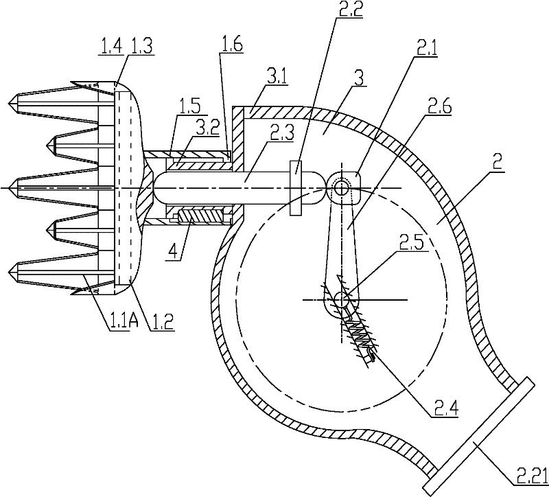
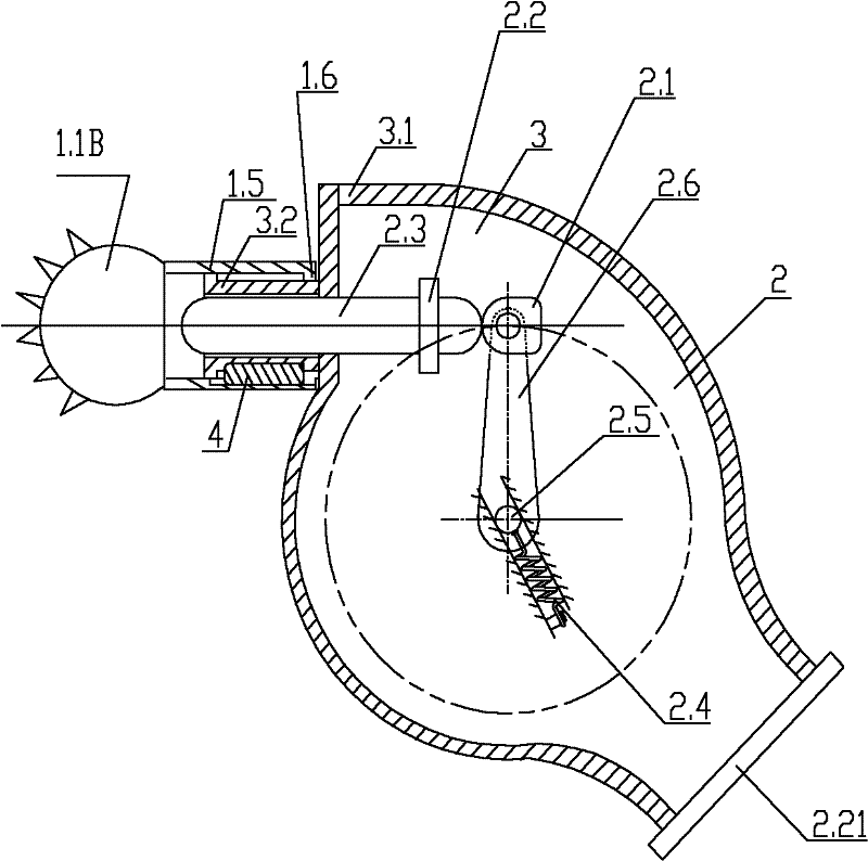
[0134] Figure 1A , Figure 1B , Figure 2A , Figure 2B It is the high-efficiency block mining machine described in Embodiment 1. The equipment includes a fuselage, an impact blanking mechanism, etc., the fuselage includes a frame, a guide device, etc., and the impact blanking mechanism is arranged on the fuselage. The impact blanking mechanism includes a shovel head or a chisel head. The impact blanking mechanism also includes an impact stroke device and an impact device. The impact stroke device is slidingly connected with the guide device. The guide device is arranged on the impact device and / or the frame. The guide device slides back and forth, the shovel head or chisel head is set at the front of the impact stroke device, the impact device impacts the impact stroke device, shovel head or chisel head, the shovel head or chisel head impacts, the impact blanking mechanism is set on the body, and the travel device Drive the fuselage to move the shovel head or chisel head ...
Embodiment 2
[0151] Figure 5It is the high-efficiency block mining machine described in Embodiment 2. In this embodiment, a buffer component 2.4 is provided on the rotating shaft 2.5 in the rotary hammer. One end of the hammer handle 2.6 is fixedly sleeved on the rotating shaft 2.5, and the other end is rotatably connected with the hammer head 2.1, so that the hammer head 2.1 can rotate smoothly so that the impact can pass smoothly after completion.
[0152] Others are with embodiment 1.
Embodiment 3
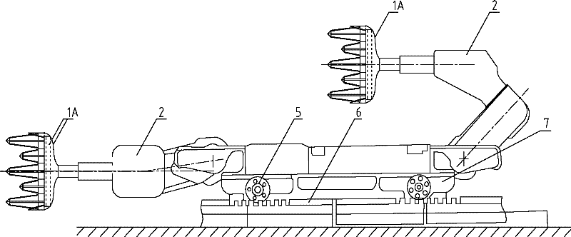
[0154] Image 6 It is the high-efficiency block mining machine described in embodiment 3. In this embodiment, the rotating shaft 2.5 is connected to the driving part 2.11 through a transmission chain or a transmission belt, and there is a certain transmission ratio between the rotating shaft 2.5 and the driving part 2.11, thereby realizing the acceleration and / or speed change of the rotating shaft 2.5, so The rotating shaft 2.5 and the drive components form a variable speed transmission. The speed change transmission device drives the hammer handle to rotate and impacts the punch rod 2.3, and the punch rod 2.3 impacts the shovel head or the chisel head to move forward. By arranging the variable speed transmission device, not only the rotation speed of the rotating shaft 2.5 can be increased, but also the reaction force produced by the hammer head in the process of impacting the punching rod can be greatly absorbed, which plays a role in protecting the driving parts and the fu...
PUM
 Abstract
Description
Claims
Application Information