LED (Light-Emitting Diode) lens device, LED lens device module and LED lamp device

A LED lens and module technology, applied in the field of lighting, can solve the problems of low illuminance uniformity and small lighting area, achieve the goals of reducing glare, increasing the lighting area and illuminance uniformity, and improving illuminance uniformity and lighting efficiency Effect

Inactive Publication Date: 2012-09-05
BEIJING UNIV OF TECH
View PDF0 Cites 29 Cited by
  • Summary
  • Abstract
  • Description
  • Claims
  • Application Information

AI Technical Summary

Problems solved by technology

[0003] The technical problem solved by the present invention is to overcome the shortcomings of the existing LED lamps such as small lighting are

Method used


Image

  • LED (Light-Emitting Diode) lens device, LED lens device module and LED lamp device
  • LED (Light-Emitting Diode) lens device, LED lens device module and LED lamp device
  • LED (Light-Emitting Diode) lens device, LED lens device module and LED lamp device

Examples


Example Embodiment

[0028] Figure 4 Is a schematic diagram of the three-dimensional structure of the LED lens device of the present invention, Figure 5 It is a schematic top view of the LED lens device of the present invention. Such as Figure 4 with Figure 5 As shown, the LED lens device of the present invention is used to cover the outside of the LED to control the light direction of the LED. It includes a parabolic concentrating bowl 1, a collimating lens 2 arranged in the parabolic concentrating bowl 1, and The compound eye lens system 3 at the open end of the parabolic condenser bowl 1, the focal point of the parabolic condenser bowl 1 coincides with the focal point of the collimating lens, and the LED is arranged at the focal point of the parabolic condenser bowl 1, so The side of the collimating lens 2 facing the LED is a free-form surface, the fly-eye lens system 3 includes a plurality of fly-eye lenses 4 arranged in an array, and the shape of the fly-eye lens 4 is a free-form surface. ...


PUM


Abstract

The invention relates to an LED (Light-Emitting Diode) lens device, an LED lens device module and an LED lamp device. The LED lens device is used for covering the exterior of an LED and controlling the light direction of the LED and comprises a parabolic light-condensing bowl, a collimating lens and a facetted-eye lens system, wherein the collimating lens is arranged in the parabolic light-condensing bowl, and the facetted-eye lens system is arranged at the opening end of the parabolic light-condensing bowl; the focal point of the parabolic light-condensing bowl is coincided with that of the collimating lens; the LED is arranged at the focal point of the parabolic light-condensing bowl; one side of the collimating lens facing the LED is of a free curved surface; the facetted-eye lens system comprises a plurality of facetted-eye lenses which are in arrayed arrangement; the shapes of the facetted-eye lenses are of free curved surfaces; and the projection of the facetted-eye lenses along the axial direction of the parabolic light-condensing bowl is rectangular.

Description

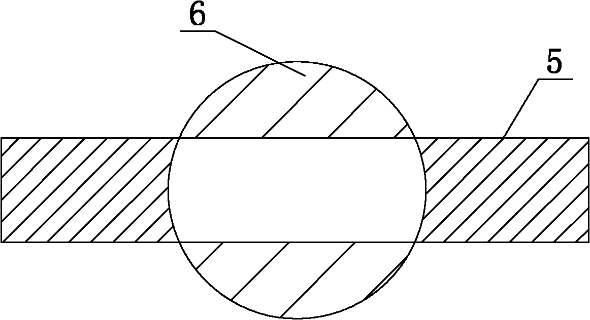
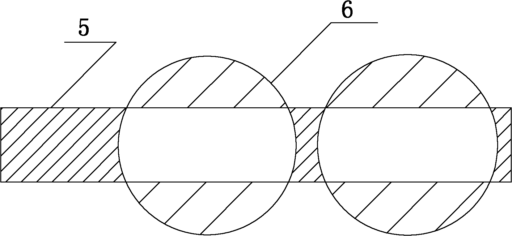
technical field [0001] The invention relates to the lighting field, in particular to an LED lens device, an LED lens device module and an LED lamp. Background technique [0002] Compared with traditional lighting sources, LED has the advantages of environmental protection, energy saving, long service life and shock resistance. With the advancement of LED technology, the stability of LED light source light efficiency and the decline of LED prices, LED lighting has changed from outdoor landscape lighting , The field of road lighting is gradually expanding to the application of urban lighting. However, compared with traditional fluorescent lamps and sodium lamps, LED lamps are smaller in size, so the light-emitting surface is also small, resulting in a small lighting area. In addition, the single light-emitting direction of LEDs further limits the lighting area. In addition, the light spot formed by the existing LED lamps is a circular light spot 6, such as figure 1 and fig...

Claims


Application Information

Patent Timeline
IPC IPC(8): F21V5/04F21Y101/02F21K9/237F21K9/66F21Y115/10
Inventor 陈建新李澄
Owner BEIJING UNIV OF TECH
Why Eureka
Try Eureka