Liquid crystal lens type dimming device and display

A liquid crystal display, liquid crystal lens technology, applied in static indicators, optics, instruments, etc., can solve the problems of increasing the brightness of the backlight panel and increasing the display cost.

Active Publication Date: 2012-09-05
BOE TECH GRP CO LTD
View PDF6 Cites 38 Cited by
  • Summary
  • Abstract
  • Description
  • Claims
  • Application Information

AI Technical Summary

Problems solved by technology

Calculated based on the above-mentioned transmittance, only 6% of the light emitted from the backlight is left. To obtain sufficient brightn

Method used


Image

  • Liquid crystal lens type dimming device and display
  • Liquid crystal lens type dimming device and display
  • Liquid crystal lens type dimming device and display

Examples


Embodiment 1

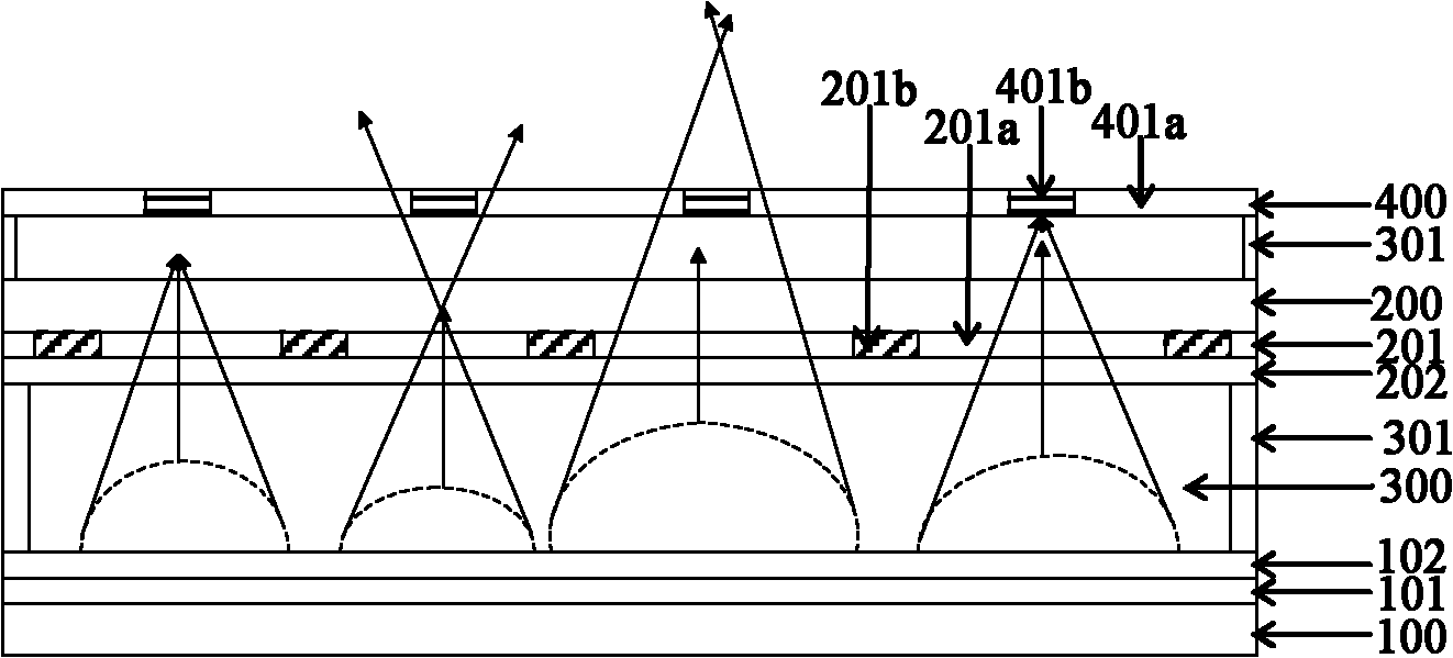
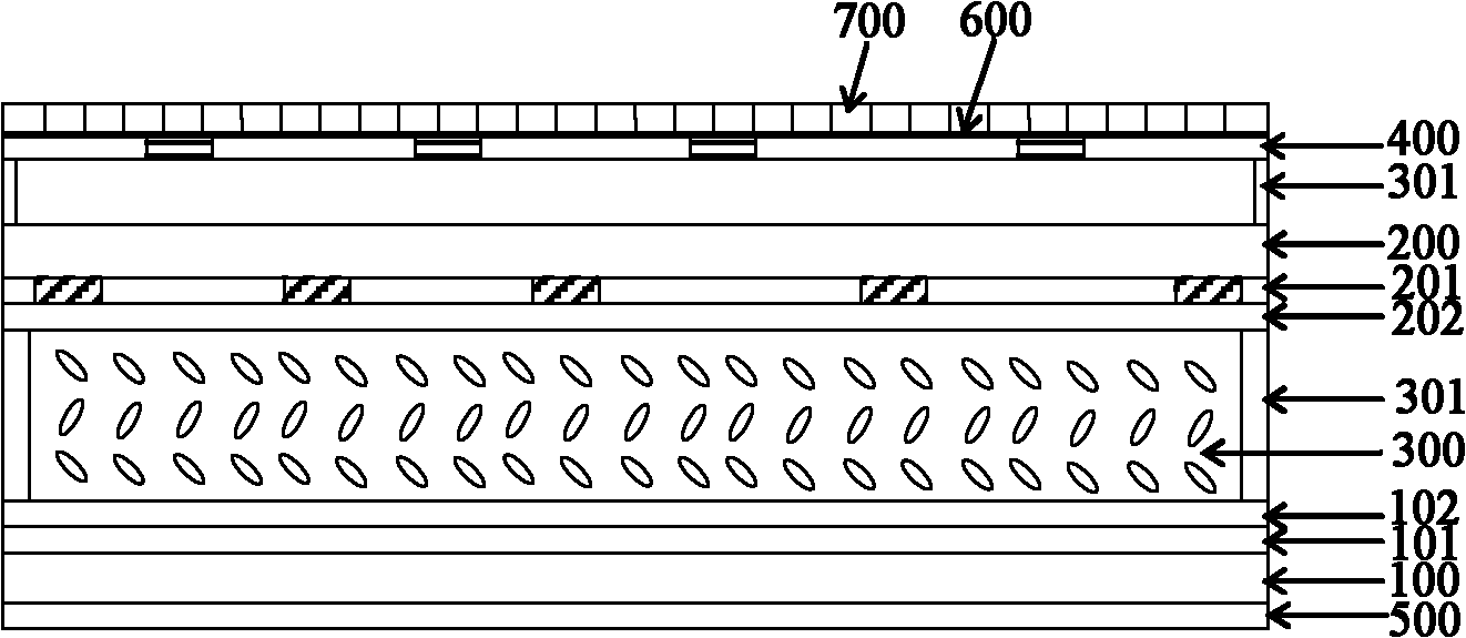
[0024] figure 1 A schematic structural diagram of the liquid crystal lens type dimming device of this embodiment is shown, the dimming device includes a first substrate 100 and a second substrate 200, the two substrates are arranged opposite to each other at a certain distance, and the first substrate 100 is located on the second substrate 200 Below, a liquid crystal is added between the two substrates, such as figure 1 In the liquid crystal layer 300 shown in , the two substrates are packaged into a cell by a sealant 301 to form a liquid crystal cell.

[0025] The upper surface of the first substrate 100 is also sequentially formed with a first electrode layer 101 and a first alignment layer 102, the first alignment layer 102 is in direct contact with the liquid crystal layer 300, and the first alignment layer 102 is used to align the liquid crystal molecules in the liquid crystal layer 300 , so that the liquid crystal molecules are arranged according to certain rules before...

Embodiment 2

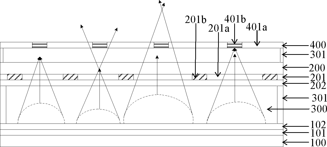
[0032]The structure of the liquid crystal lens type dimming device provided in this embodiment is similar to that of Embodiment 1, the difference is that the first electrode layer 101 of this embodiment is a patterned electrode, the second electrode layer 201 is a surface electrode, and the second electrode layer 201 is a surface electrode. When the first electrode layer 101 is used as a patterned electrode, its structure and relative positional relationship with the baffle 400 are the same as that of the second electrode layer 201 in Embodiment 1 when used as a patterned electrode. Specifically, the first electrode layer 101 includes a plurality of first electrode regions and first electrode light-shielding regions distributed at intervals, and the first electrode layer 101 is connected with an electrode voltage control circuit to separately control the voltage of each first electrode region in the patterned electrode. and each barrier light-shielding region 401b is located ab...

Embodiment 3

[0034] The structure of the liquid crystal lens type dimming device provided in this embodiment is similar to that of Embodiment 1, the difference is that the first electrode layer 101 of this embodiment is also a patterned electrode, specifically, the first electrode layer 101 includes A plurality of first electrode regions and first electrode light-shielding regions distributed at intervals, the first electrode layer 101 is connected with an electrode voltage control circuit to respectively control the voltage on each first electrode region in the patterned electrodes. In addition, each electrode area of ​​the second electrode layer 201 is respectively located above an electrode area of ​​the first electrode layer 101, and the structure of the baffle plate 400 and its relative positional relationship with the second electrode layer 201 remain unchanged, which is the same as in Embodiment 1. same.


PUM


Abstract

The invention discloses a liquid crystal lens type dimming device, comprising a first substrate, a second substrate, electrode layers and orientation layers, wherein the electrode layer and the orientation layer are arranged on each one of the first substrate and the second substrate; liquid crystal is added between the two substrates, and is packaged in a box by frame packaging glue to form a liquid crystal lens; one or two electrode layers on the two substrates comprises/comprise pattered electrode/electrodes in an electrode area and a shading area; a baffle is arranged above the second substrate; the baffle comprises a baffle light-transmitting area and a baffle shading area; the baffle shading area is less than the electrode area in the pattered electrode/electrodes in area, and is located above the electrode area; and the two electrode layers are respectively connected with an electrode voltage control circuit. The liquid crystal lens type dimming device provided by the invention obtains a proper lens focal distance by adjusting a voltage between the electrodes, the intensity of light bypassing the baffle is adjusted, and a backlight use ratio is improved. Furthermore, a backlight source, a colorful filtering sheet, a reflection layer, a diffusion sheet and the like are additionally arranged, so that the dimming device is used for the display. The dimming device further can be used for the application, such as detection and receiving of light signals.

Description

technical field [0001] The invention relates to liquid crystal display technology, in particular to a liquid crystal lens type dimming device and a display. Background technique [0002] One of the most important specifications in liquid crystal displays is brightness, and the most important factor in determining brightness is the aperture ratio. Simply put, the aperture ratio is the ratio of the effective area through which light can pass. When the light is emitted through the backlight panel, not all the light can pass through the panel, such as the signal wiring for the liquid crystal display source driver chip and gate driver chip, as well as the TFT itself, as well as the storage for voltage storage. capacitance and so on. In addition to the incomplete light transmission in these places, because the light passing through these places is not controlled by the voltage, the correct gray scale cannot be displayed, so they must be covered with a black matrix, so as not to ...

Claims


Application Information

Patent Timeline
IPC IPC(8): G02F1/133G02F1/29G02F1/1343G02F1/1337G02F1/1335G02F1/13357
CPCG02F1/133512G02F2203/28G02F2203/48G02F1/294G02F1/133526G02F1/133606G02F1/133611
Inventor 张卓
Owner BOE TECH GRP CO LTD
Why Eureka
Try Eureka