Steel pipe cutting machine tool

A technology for cutting machine tools and cutting mechanisms, which is applied in the direction of sawing machine devices, metal sawing equipment, metal processing machinery parts, etc., and can solve the problems of large vibration energy loss and material loss, large cutting noise and surrounding environmental pollution, and low precision and smoothness of cutting sections. and other problems, to achieve the effect of reducing energy loss and material loss, improving precision and smoothness, and thin saw blade thickness

Inactive Publication Date: 2012-09-12
贺伟
View PDF7 Cites 17 Cited by
  • Summary
  • Abstract
  • Description
  • Claims
  • Application Information

AI Technical Summary

Problems solved by technology

Therefore, the vibration and energy loss and material loss during the sawing process are quite large
The other two shortcomings are: the accuracy and smoothness of the cutting section are low, the cutting

Method used


Image

  • Steel pipe cutting machine tool
  • Steel pipe cutting machine tool
  • Steel pipe cutting machine tool

Examples


Embodiment Construction

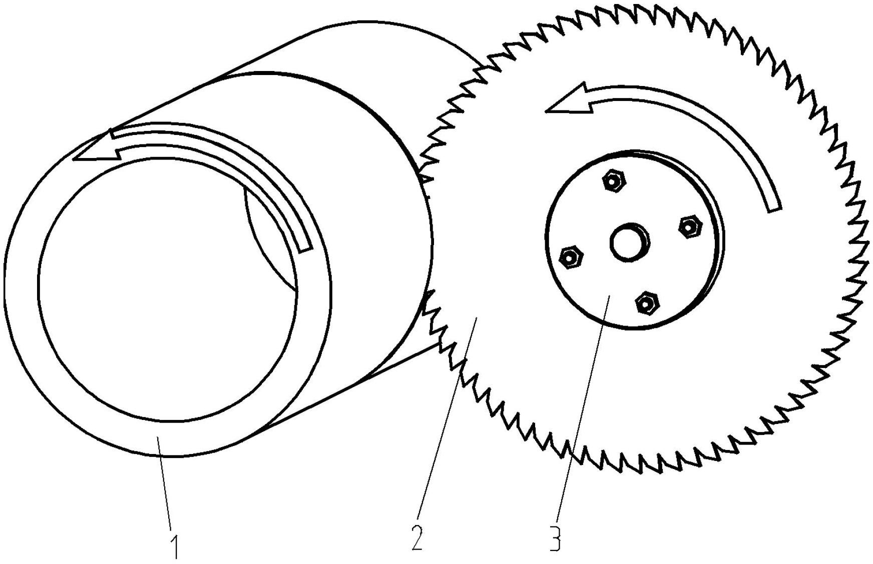
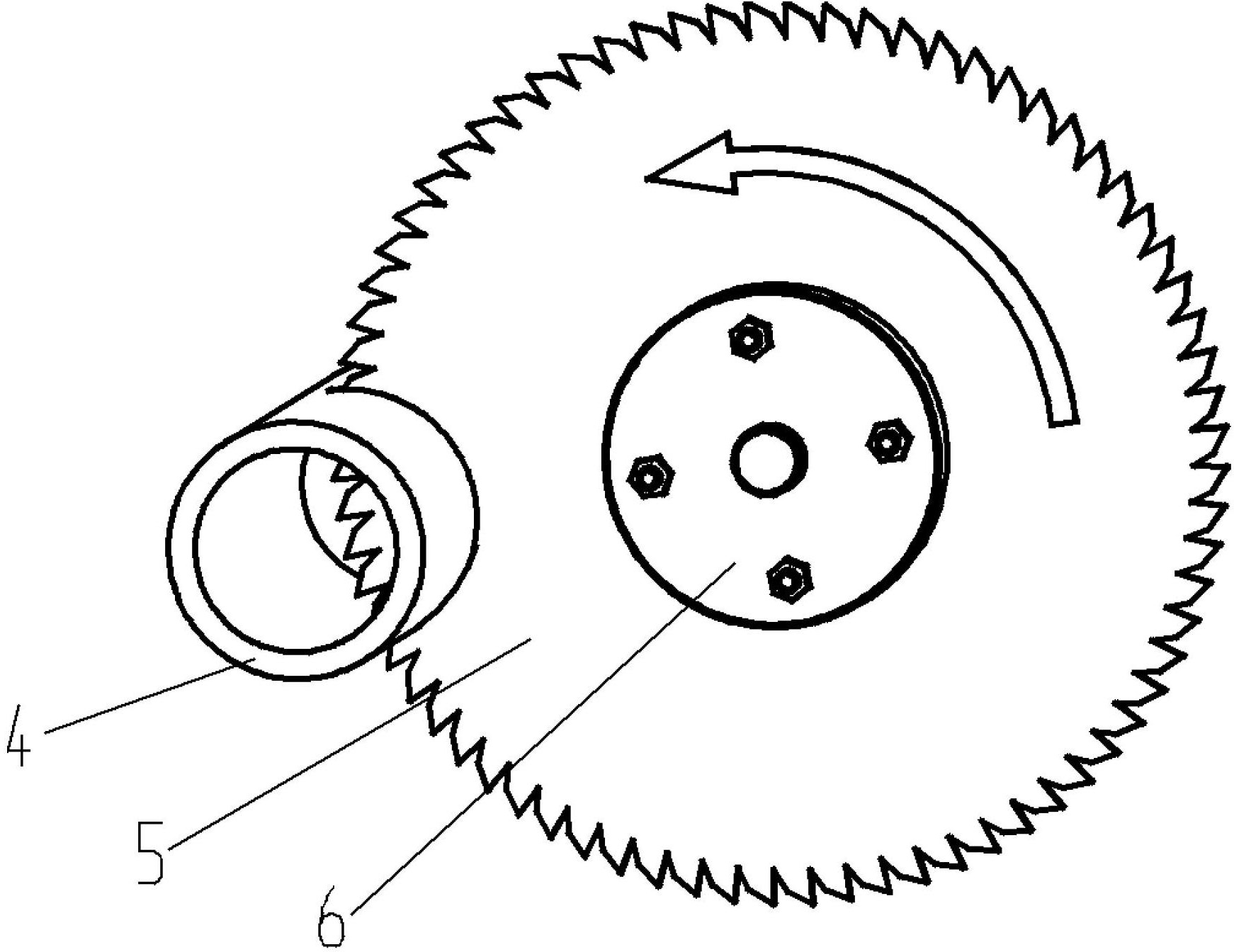
[0073] The invention discloses a steel pipe cutting machine tool, which is used for improving the cutting speed and cutting efficiency of steel pipes, and reducing material loss and energy loss in the cutting process.

[0074] figure 1 Schematic diagram of sawing provided for the embodiment of the present invention;

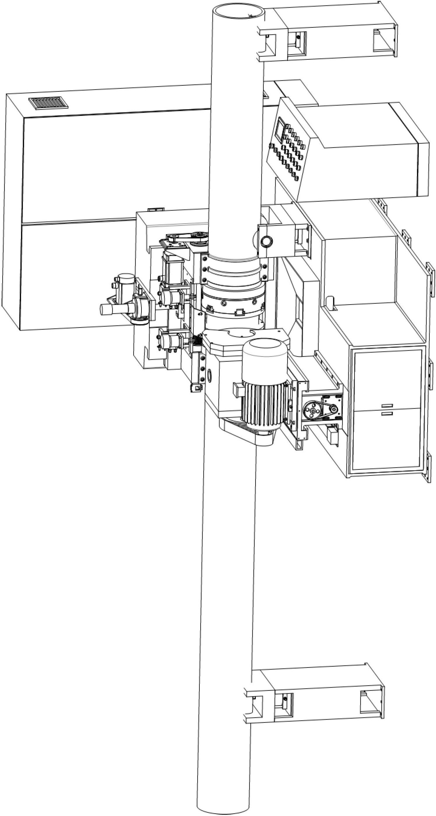
[0075] image 3 , Figure 4 and Figure 5 The overall assembly drawing of the cutting machine tool provided by the embodiment of the present invention.

[0076] The following will clearly and completely describe the technical solutions in the embodiments of the present invention with reference to the accompanying drawings in the embodiments of the present invention. Obviously, the described embodiments are only some, not all, embodiments of the present invention. Based on the embodiments of the present invention, all other embodiments obtained by persons of ordinary skill in the art without making creative efforts belong to the protection scope of the presen...


PUM


Abstract

The invention discloses a steel pipe cutting machine tool, which is used for cutting large/medium-caliber steel pipes, and comprises a spindle rotating mechanism, a spindle lifting mechanism, a cutting mechanism, a supporting mechanism and a chuck clamping and unclamping device. According to the steel pipe cutting machine tool, a cutting mode of simultaneously rotating a saw blade and the steel pipes along an axis is adopted, when the saw blade rotates at a high speed and feeds and cuts the steel pipes along the radial direction of the steel pipes, the steel pipes rotate around the own axis at low speed, so that the saw blade cuts the steel pipes toward the axis along the outer circumference of the steel pipe; and therefore, the steel pipes can be cut off when the inner walls of the steel pipes are cut by the saw blade. Compared with the prior art, the steel pipe cutting machine tool has the advantages that the feeding distance is greatly shortened, the cutting speed is increased, the diameter of the saw blade is not required to be large, the thickness of the saw blade is small, and the precision and finish of the cutting section are greatly improved; and meanwhile, the energy loss and material loss of the steel pipe cutting machine tool are greatly reduced, and the current industrial requirements for environment friendliness and low carbon are met.

Description

technical field [0001] The invention relates to the technical field of machine tools, in particular to a steel pipe cutting machine tool. Background technique [0002] After the steel pipe is rolled on the production line, its two ends are irregular due to the extrusion deformation during rolling. At this time, the irregular parts at the two ends of the steel pipe must be sawed off to make it a qualified product and leave the factory. [0003] In the prior art, there are mainly three methods for sawing steel pipes: band sawing machine, large-scale circular sawing machine and large-scale sand wheel cutting machine. [0004] Although the sawing cost of the band sawing machine is relatively low, it is not suitable for the fast-paced work of the steel pipe production line due to the flexibility of the band saw blade, which is easy to saw the section off, and its speed is too slow. [0005] The sawing speed of circular sawing machine and sand wheel cutting machine is faster, whi...

Claims


Application Information

Patent Timeline
IPC IPC(8): B23D47/04B23D47/12B23Q5/10
Inventor 贺伟
Owner 贺伟
Why Eureka
Try Eureka