Surface emitting laser packaging fixture

A surface-emitting laser and clamping technology, which is applied in auxiliary devices, manufacturing tools, auxiliary welding equipment, etc., can solve the problems of easy-to-deviate tube shells, poor fixation of heat sinks, and poor mobility, so as to improve efficiency and improve The effect of fixed efficiency and simple structure

Inactive Publication Date: 2012-09-12
CHANGCHUN INST OF OPTICS FINE MECHANICS & PHYSICS CHINESE ACAD OF SCI
View PDF6 Cites 10 Cited by
  • Summary
  • Abstract
  • Description
  • Claims
  • Application Information

AI Technical Summary

Problems solved by technology

[0004] In order to solve the defects of high welding cost, poor mobility, easy deviation, and poor fixation of the shell and heat sink of the packaging machine for packaging and welding surface-emitting lasers, the present invention proposes a surface-emitting laser packaging fixture

Method used


Image

  • Surface emitting laser packaging fixture
  • Surface emitting laser packaging fixture
  • Surface emitting laser packaging fixture

Examples


specific Embodiment approach 1

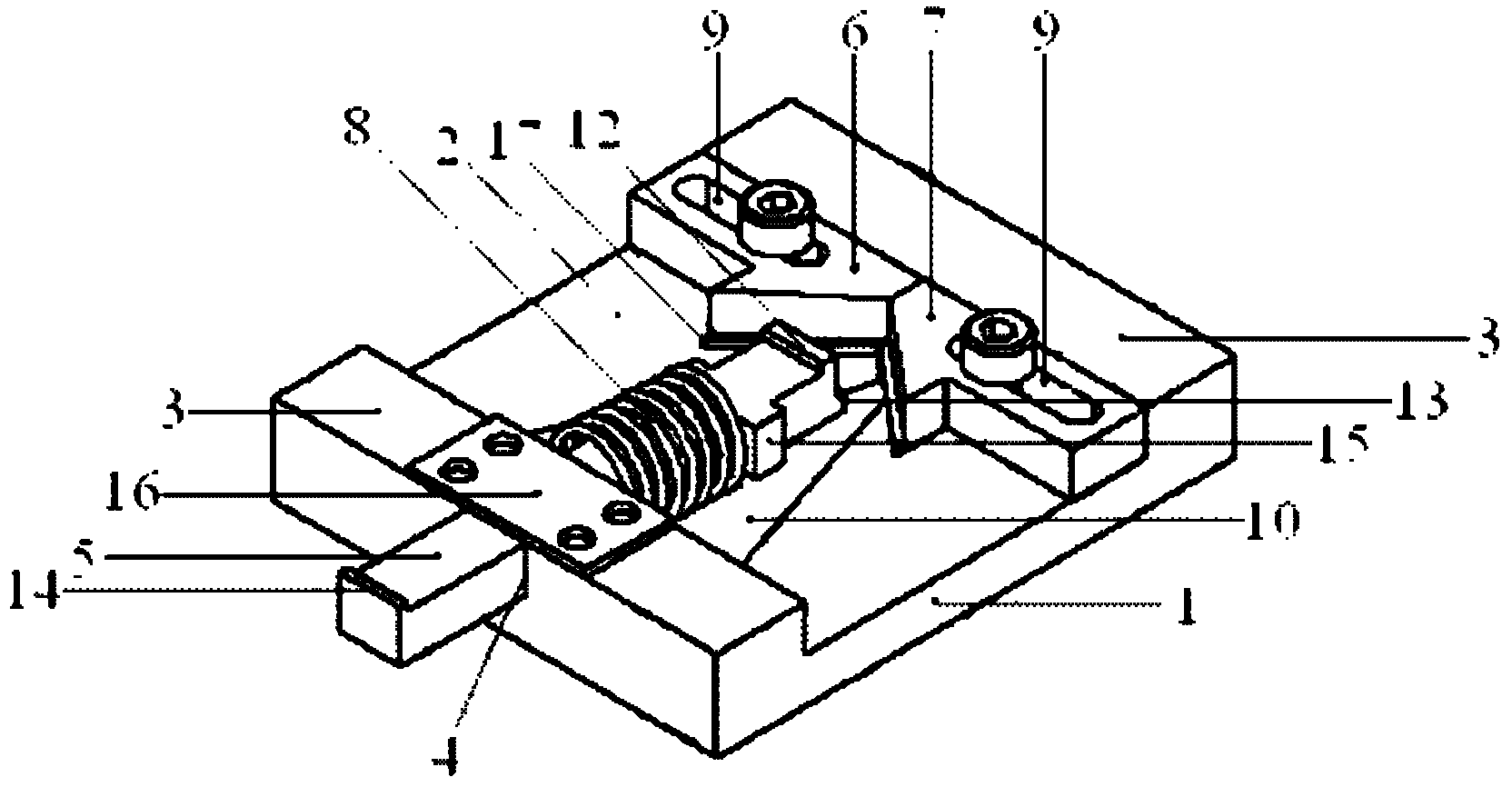
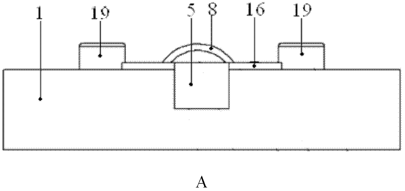
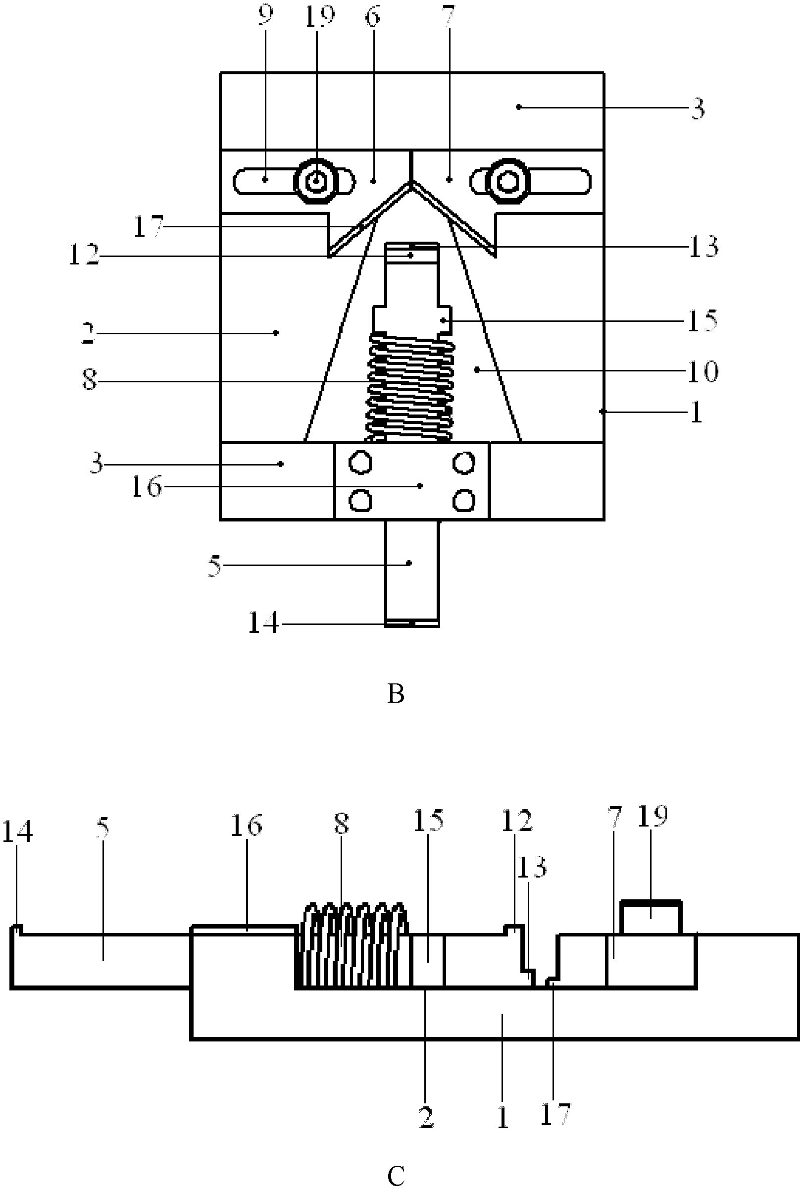
[0017] Specific implementation mode 1. Combination figure 1 Describe this embodiment, as shown in the figure, the surface-emitting laser packaging fixture of the present invention includes a fixture body 1, a rectangular sinking structure 2 is arranged in the middle of the fixture body 1, and raised structures 3 of the same width are respectively arranged at both ends, There is a sliding groove 4 in the middle of the protruding structure 3 at one end, which is characterized in that it also includes a push rod 5, a left tightening part 6 and a right tightening part 7. The push rod 5 passes through the sliding groove 4 and is movably connected with the clamp main body 1, and the spring 8 is inserted into the ejector rod 5, and the left tightening part 6 and the right tightening part 7 are respectively provided with length adjustment grooves 9, and the positions of the left tightening part 6 and the right tightening part 7 in the length adjustment groove 9 are aligned with the pos...

specific Embodiment approach 2

[0024] Embodiment 2. The difference between this embodiment and Embodiment 1 is that this embodiment is a specific example of Embodiment 1.

[0025] The surface-emitting laser packaging fixture of the present invention is suitable for packaging and welding the surface-emitting laser on the shell or heat sink. The diameter of the shell or heat sink is required to be 5.4mm, the height is 12mm, and the size of the surface-emitting laser is 1mm×1mm.

[0026] The fixture main body 1, ejector rod 5, left tightening part 6 and right tightening part 7 of the surface emitting laser packaging fixture of the present invention are all made of aluminum material, and the shape of the above-mentioned parts is processed by a wire cutting method, and the above-mentioned parts are polished by a machine. Polish the surface, and then use ultrasonic cleaning and drying to form.

[0027] The fixture main body 1 is an axisymmetric structure, the length, width and height of the fixture main body 1 ar...

specific Embodiment approach 3

[0030] Embodiment 3. The difference between this embodiment and Embodiment 1 is that this embodiment is a specific working process of Embodiment 1.

[0031] combine Figure 7 To illustrate this embodiment, when the surface-emitting laser packaging fixture of the present invention is working, the left tightening component 6 and the right tightening component are adjusted by adjusting the positions of the screws 19 on the left tightening component 6 and the right tightening component 7 in the length adjustment groove 9. The distance between 7 is increased to an appropriate width, slide the ejector rod 5, so that the front desk 13 on the ejector rod 5 is separated from the left tightening part 6 and the right tightening part 7 by a suitable distance, and the base of the TO-46 tube shell 18 is placed on the left tightening On the protruding platform 17 of the component 6 and the right tightening component 7, use the pressure of the spring 8 to reset the ejector rod 5 and fix it wi...


PUM


Abstract

The invention discloses a surface emitting laser packaging fixture, relates to the technical field of semi-conductor optoelectronics, solves the problem that a packaging machine for packaging a surface emitting laser is high in welding cost, poor in mobility, and infirm in fixing and has deviation easily. The surface emitting laser packaging fixture comprises a fixture main body; the middle of the fixture main body is provided with a rectangular sinking structure, and two ends of the fixture main body are provided with bulge structures in the same width; the middle of a bulge structure at one end is provided with a sliding groove; the fixture also comprises an ejector rod, a left fastening part and a right fastening part; the ejector rod penetrates through the sliding groove and is movably connected with the fixture main body; a spring is sleeved in the ejector rod; the left fastening part and the right fastening part are respectively provided with a length adjusting groove; and the left fastening part and the right fastening part are fixed with the fixture main body through adjusting screws in the length adjusting grooves. The surface emitting laser packaging fixture is simple in structure, high in mobility, small in deviation and easy and convenient to operate, and improves the efficiency of a welding process.

Description

technical field [0001] The invention relates to the technical field of semiconductor optoelectronics, in particular to a surface-emitting laser packaging fixture. Background technique [0002] The packaging and welding of surface-emitting lasers generally adopts ultrasonic gold wire welding or soldering on the heat sink. There is no movement in the position of the shell or heat sink. [0003] At present, the packaging and welding of surface-emitting lasers adopts large-scale packaging machines with relatively complex structures. This packaging machine is not only expensive, but also has high welding costs, and its position is relatively fixed and difficult to move, and its mobility is poor. The tube shell or heat sinks of different shapes are not firmly fixed, and the packaging and welding process is prone to deviation. Contents of the invention [0004] In order to solve the defects of high welding cost, poor mobility, easy deviation, and unstable fixing of the shell an...

Claims


Application Information

Patent Timeline
Patent Type & Authority Applications(China)
IPC IPC(8): B23K37/04
Inventor 张金胜宁永强张金龙张艳
Owner CHANGCHUN INST OF OPTICS FINE MECHANICS & PHYSICS CHINESE ACAD OF SCI
Why Eureka
Try Eureka