Gas drive type underwater disconnecting device

A technology of pneumatic drive and release device, which is applied in the directions of underwater operation equipment, transportation and packaging, ships, etc., can solve the problems of inapplicability of underwater electric manipulators, etc., and achieve the effects of light weight, guaranteed reliability and small size

Inactive Publication Date: 2012-09-12
HARBIN ENG UNIV
View PDF8 Cites 15 Cited by
  • Summary
  • Abstract
  • Description
  • Claims
  • Application Information

AI Technical Summary

Problems solved by technology

The electric manipulator is different. After the mechanical body is separated, there are still power and signal cables connected, and an additional cable disconnection mechanism is required. Therefore, the above-mentioned device is not suitable for underwater electric manipulators.
[0004] In addition, the dumping device involving the separati

Method used


Image

  • Gas drive type underwater disconnecting device
  • Gas drive type underwater disconnecting device
  • Gas drive type underwater disconnecting device

Examples


specific Embodiment approach 1

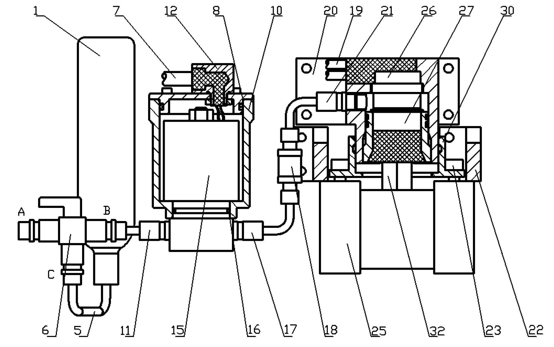
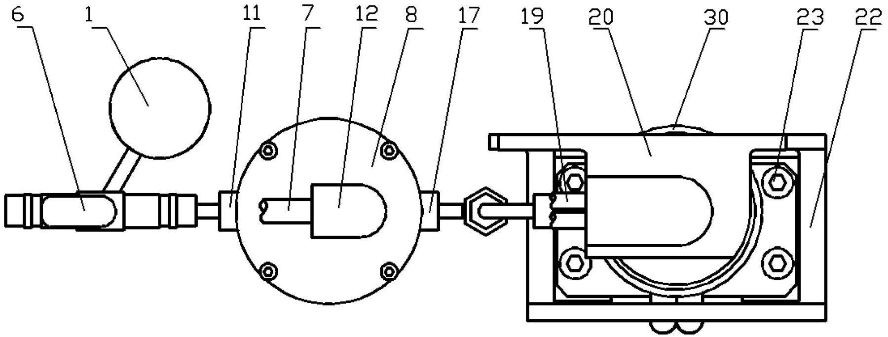
[0034] Such as figure 1 and figure 2 As shown, the present invention is mainly composed of three parts: a high-pressure gas cylinder assembly, a high-pressure solenoid valve assembly, and an emergency release mechanical body assembly. A three-way ball valve 6 is installed between the high-pressure gas cylinder assembly and the high-pressure solenoid valve assembly. A one-way valve 18 is installed between the components of the mechanical body, and each part is connected by a stainless steel high-pressure steel pipe and a high-pressure pipe joint.

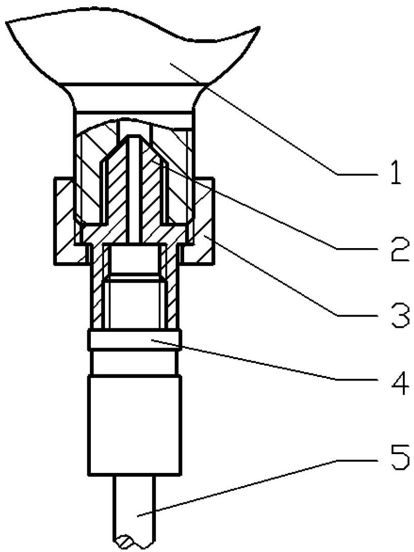
[0035] Such as image 3 As shown, the bottle mouth of the high-pressure gas cylinder 1 is processed with external threads, and the front end of the gas cylinder valve joint 2 is tightly pressed against the inner side of the bottle mouth under the extrusion of the nut 3 to complete the seal. The stainless steel high-pressure pipe joint 4 passes through the sealing pipe thread It is connected with the gas cylinder valve joint 2, and...

specific Embodiment approach 2

[0042] Such as Figure 10 As shown, a set of high-pressure solenoid valve assembly is added on the basis of Embodiment 1. Add threaded holes on the right side of the fixed base 20, connect with the high-pressure pipe joint 34 through the sealing pipe thread, and then connect with the high-pressure solenoid valve 37 valve body through the high-pressure steel pipe 35 and the high-pressure pipe joint 36, and the left end of the high-pressure pipe joint 38 passes through the sealing pipe Thread links to each other with high pressure electromagnetic valve 37 valve bodies, and the right end connects oil bag 39, is full of hydraulic oil in the oil bag 39. When the underwater equipment works normally, the solenoid valve 15 is in a normally closed state, while the solenoid valve 37 is in a normally open state. The hydraulic oil in the oil bag 39 enters the inner cavity of the fixed base 20 through the electromagnetic valve 37 and the steel pipe 35, so that the inner cavity pressure of...


PUM


Abstract

The invention provides a gas drive type underwater disconnecting device, mainly comprising three parts including a high pressure gas cylinder assembly, a high pressure electromagnetic valve assembly and a mechanical body assembly, wherein the three parts are connected through a stainless steel high pressure steel pipe and a high pressure pipe joint. A three-way ball valve is installed between the high pressure gas cylinder assembly and the high pressure electromagnetic valve assembly, and a one-way valve is installed between the high pressure electromagnetic valve assembly and the mechanical body assembly. The high pressure gas cylinder assembly is used for storing high pressure gas, the high pressure electromagnetic valve assembly is used for controlling the on-off of the high pressure gas in a pipeline, the mechanical body assembly is used for separating machinery and cables of a manipulator and underwater operation equipment, the three-way ball valve is used for changing gas circuits, and the one-way valve is used for preventing sea water from flowing into the gas cylinder after the manipulator is disconnected. When the underwater operation equipment normally works, the gas drive type underwater disconnecting device can provide accurate installation positioning for hand and shoulder joints of the manipulator and can be reliably connected with the underwater operation equipment. When the manipulator is in a dangerous condition, reliable separation of the manipulator and the underwater operation equipment can be realized so that the underwater operation equipment can be separated from the dangerous condition.

Description

technical field [0001] The patent of the present invention relates to an underwater release device, specifically a device capable of realizing emergency separation of machinery and cables between an underwater electric manipulator and an underwater operation equipment body. Background technique [0002] The ocean is rich in biological resources and mineral resources, and the development and utilization of the ocean by human beings is inseparable from underwater operation equipment. The underwater electric manipulator is a work tool that is often equipped with underwater work equipment. Due to the complex underwater operation environment, when the underwater equipment is performing underwater operations, the manipulator may be entangled by aquatic plants, fishing nets, cables or stuck by underwater stones, causing the operating equipment to lose mobility or even crash. At this time, quickly Getting rid of the manipulator is the only way for underwater equipment to save itsel...

Claims


Application Information

Patent Timeline
IPC IPC(8): B25J19/06B63C11/52
Inventor 张铭钧殷宝吉王玉甲赵文德徐建安褚振忠彭生全刘立刚
Owner HARBIN ENG UNIV
Why Eureka
Try Eureka