Al technical title is built by PatSnap Al team. It summarizes the technical point description of the patent document.
A technology for radial tires and belts, applied to tires, electric speed/acceleration control, and other household appliances, can solve problems such as deformation, difficulty in penetrating high-energy rays, and consistent performance of rubber-coated steel wire belts
Active Publication Date: 2015-02-25
BEIJING RADIATION APPL RES CENT
View PDF3 Cites 0 Cited by
Summary
Abstract
Description
Claims
Application Information
AI Technical Summary
This helps you quickly interpret patents by identifying the three key elements:
Problems solved by technology
Method used
Benefits of technology
Problems solved by technology
In these processes, it is inevitable that the steel wire belt will be stressed, and the raw rubber strength of the steel wire belt after rubber coating is low, and it is easy to deform after being stressed.
These forces and deformations will lead to changes in the angle of the steel wires in the steel belt layer, or cause inconsistent thicknesses of raw rubber on both sides of the belt layer after rubber coating
At present, the traditional steel wire belt production line can only complete the basic requirements such as gluing and cutting, and it is difficult to ensure that the semi-finished steel wire belt after gluing will not be deformed in the subsequent process.
Since the steel cord has a shielding effect on high-energy rays, it is difficult for the high-energy rays generated by the conventional electron beamer to penetrate it and irradiate the rubber on the other side of the steel wire, so it is difficult to improve the performance of the rubber-coated steel wire belt by single-sided irradiation. consistent, thus requiring a production process with double-sided irradiation
Method used
Image
Click on the blue label to locate the original text in one second.
Reading with bidirectional positioning of images and text.
Examples
Embodiment Construction
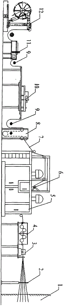
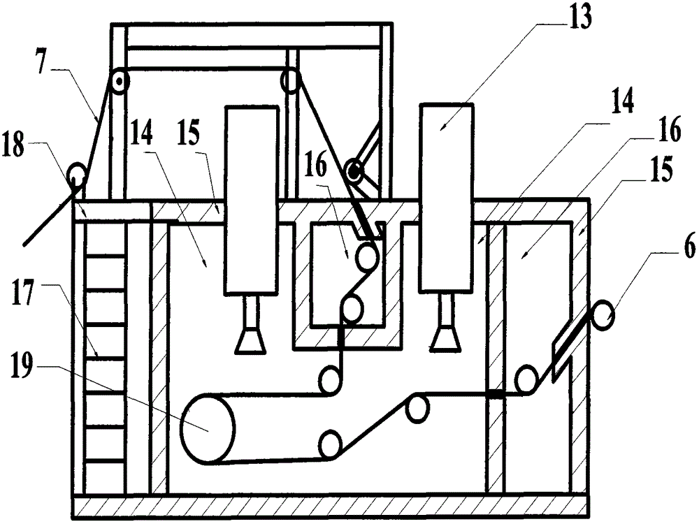
[0012] Attached below figure 1 And attached figure 2 Describe the present invention in detail, a device assembly for manufacturing radial tire belt components, including a spindle room 1, a warping frame 2, a cold feed extruder 3, a cooling device 4, a self-shielding irradiation device 5, a beam under Transmission device 6, cloth storage rack 8, photoelectric controller 9, cutting joint device 10, extrusion hemming device 11 and double-station coiling device 12, the characteristics of which are: the steel wire is unwound between the spindles 1 and maintains a constant tension The preliminary radial arrangement and arrangement of the steel wires are completed through the warping frame 2 to form a steel wire belt, which enters the cold feed extruder 3, and the rubber compound is covered around the steel wires in the cold feed extruder 3, and extruded Form a tire belt layer 7 of a flat steel wire belt with steel wire as the radial skeleton material and rubber compound as the co...
PUM
Property
Measurement
Unit
diameter
aaaaa
aaaaa
Abstract
The invention discloses an assembly for producing radial tire belt parts, which comprises a spindle chamber, a warping creel, a cold feed extruder, a cooler, a self-shielding irradiator, an under-beam conveyer, an accumulator, photoelectric controllers, a cutting and splicing mechanism, an extruding and binding mechanism and a double-station rolling mechanism, steel wires are opened in the spindle chamber and arranged into a steel wire belt by the warping creel, the steel wire belt enters the cold feed extruder, and is covered with rubber and extruded into a rubber-covered tire belt, the rubber-covered tire belt is cooled by the cooler, conveyed into the self-shielding irradiator by the under-beam conveyer, irradiated by the high-energy electron rays emitted by two electron accelerators mounted in an irradiation chamber and then arranged and accumulated in the accumulator, the rubber-covered tire belt is controlled by the photoelectric controllers to enter the cutting and splicing mechanism, and is cut and transversely spliced into steel wire belt blocks, the steel wire belt blocks are bound by the extruding and binding mechanism, so that radial tire belt parts are produced, and the radial tire belt parts are rolled by the rolling mechanism for later use. The assembly is easy to operate, operation is stable, the production efficiency is high, the operation cost is low, and the assembly can be conveniently seamlessly connected with a production line.
Description
Technical field [0001] The invention relates to the technical field of rubber tire processing, in particular to a device assembly for manufacturing belt parts of radial tires. Background technique [0002] The steel belt layer extrusion rubber coating production line is one of the key equipment for the production of semi-steel radial tires. At present, the main functions of the traditional steel belt production line are to complete the rubber coating, cooling, cutting, jointing, hemming and coiling of the steel cord. In the tire production process, there are two main requirements for the steel wire belt layer. One is to ensure that the steel wires in the steel wire belt layer are evenly distributed and not deformed, and the angle of the steel wires does not change during the production process; the other is to ensure the thickness of the rubber on both sides of the steel wire. Consistent, other rubber materials must not penetrate into the steel cord layer, affecting the adh...
Claims
Application Information
Patent Timeline
Application Date:The date an application was filed.
Publication Date:The date a patent or application was officially published.
First Publication Date:The earliest publication date of a patent with the same application number.
Issue Date:Publication date of the patent grant document.
PCT Entry Date:The Entry date of PCT National Phase.
Estimated Expiry Date:The statutory expiry date of a patent right according to the Patent Law, and it is the longest term of protection that the patent right can achieve without the termination of the patent right due to other reasons(Term extension factor has been taken into account ).
Invalid Date:Actual expiry date is based on effective date or publication date of legal transaction data of invalid patent.