Hydraulic system of numerical control turrent punch press and working method of hydraulic system

A technology of CNC turret punch press and hydraulic system, which is applied in the field of hydraulic system to achieve the effect of light action, high operation rate and filling the technical gap

Active Publication Date: 2012-09-12
扬州九龙湾园林工程有限公司
View PDF11 Cites 9 Cited by
  • Summary
  • Abstract
  • Description
  • Claims
  • Application Information

AI Technical Summary

Problems solved by technology

[0011]1) The procurement cost is high; at present, the company’s product is in a monopoly position in the world, and the price is controlled by it, which makes the procurement cost expensive and eventually leads to the failure of the whole machine. Increased costs;
[0012]2), the oil circuit is complicated, and the failure rate is high; due to the use of three "power sources" of double pumps and accumulators, the three "power sources" The oil circuit needs to pass through several hydraulic components and the main cylinder to form a working circuit, which makes the whole oil circuit particularly complicated and has a high failure rate;
[0013]3) The oil return vibration is large, so a buffer needs to be installed; due to the use of a large flow pump, the return oil flow is large, and it is easy to generate large vibration during the return journey ;
[0014]4) Large flow rate requires the use of large-diameter valves; high-pressure pumps output high-pressure and small-flow hydraulic oil, and low-pressure pumps output low-pressure and large-flow hydraulic oil, requiring large-diameter hydraulic pipes The oil circuit can meet the needs of the oil circuit; and when the hydraulic pipeline has a large diameter, the corresponding equipment cost and occupied space are also high;
[0015]5), low energy efficiency; two pumps are used, which makes the overall operation consume a lot of energy and the energy efficiency conversion rate is low

Method used


Image

  • Hydraulic system of numerical control turrent punch press and working method of hydraulic system
  • Hydraulic system of numerical control turrent punch press and working method of hydraulic system
  • Hydraulic system of numerical control turrent punch press and working method of hydraulic system

Examples


Embodiment Construction

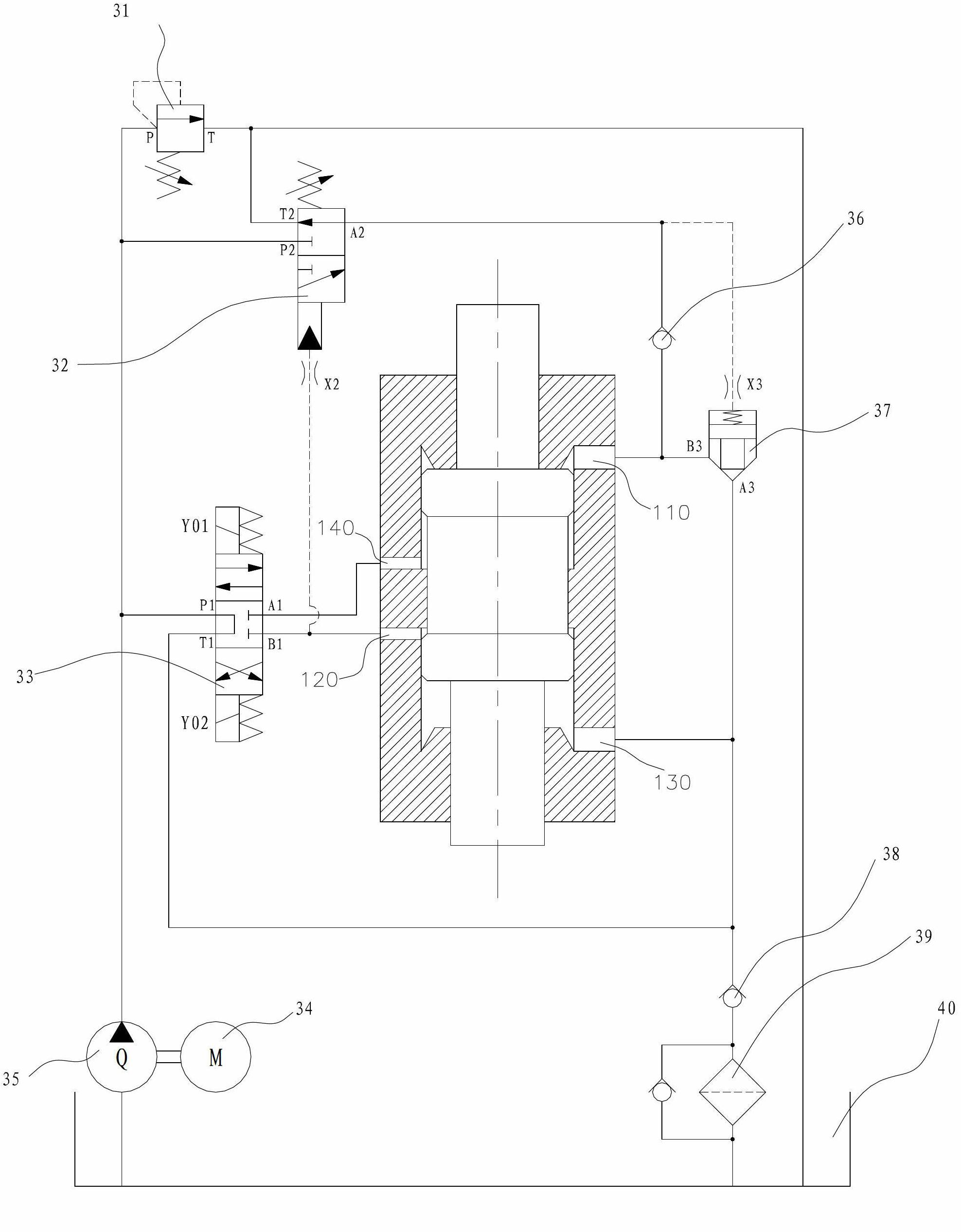
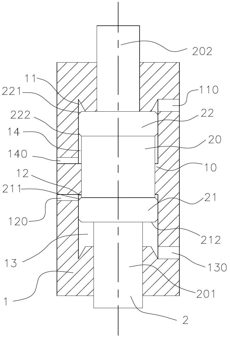
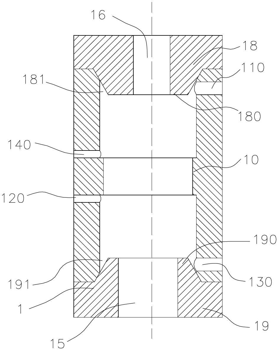
[0062] The invention patent as Figure 1-9 As shown, it includes a striking head driving cylinder and a hydraulic drive circuit, and the striking head driving cylinder includes a cylinder body 1 with a multi-shouldered piston 2

[0063] The cylinder block 1 includes a working oil inlet port 110, a fast oil inlet port 120, a fast retreat oil port 140, an oil return port 130 and a circle of bosses 10 arranged in the middle of the inner wall of the cylinder block 1;

[0064] The piston 2 includes a piston body 20 and a drive rod 201 arranged at the lower end of the piston body 20. The outer edge of the top end surface of the piston body 20 is provided with a circle of upper shoulders 22, and the outer edge of the bottom end surface is provided with a circle of lower shoulders. 21: Forming the multi-shouldered piston body structure.

[0065] The hydraulic drive circuit includes a fuel tank 40, a hydraulic pump 35, a three-position four-way electromagnetic reversing valve 33, a tw...


PUM


Abstract

The invention discloses a hydraulic system of a numerical control turrent punch press and a working method of the hydraulic system, and relates to a driving hydraulic system of a punch head of a high-speed numerical control turrent punch press and a working method of the driving hydraulic system. On the premise that requirements on three working processes and high-frequency working are met, the structure of the hydraulic system is simpler, energy consumption is lower, and an import like product can be replaced by the aid of the hydraulic system of the numerical control turrent punch press and the working method of the hydraulic system. The hydraulic system comprises an impact head driving cylinder and a hydraulic driving loop, the impact head driving cylinder consists of a cylinder body and a piston with multiple shoulders, and the cylinder body consists of a progressive oil port, a fast forward oil port, a fast backward oil port, an oil return port and a boss arranged in the middle of the inner wall of the cylinder body. The working method is implemented according to steps of 1), initiating a station; 2) fast forwarding the piston; 3) progressively feeding the cylinder; and 4) fast reversing the cylinder so that a working cycle is completed. The hydraulic system and the working method have the advantages that overseas technical barriers in the field of high-speed numerical control plate processing equipment are broken through, the current situation of overseas monopolization is also broken, and a national technical gap is filled.

Description

technical field [0001] The invention relates to a hydraulic system of a high-speed numerical control stamping machine tool and a working method thereof, in particular to a hydraulic system for driving a stamping head of a high-speed numerical control turret punching machine and a working method thereof. Background technique [0002] With the progress of the times, the development of science and technology, and the improvement of productivity, ordinary mechanical CNC turret punches tend to be replaced by hydraulic CNC turret punches due to their shortcomings such as slow punching speed and high noise. Due to the limitation of technical conditions and industrial level, the hydraulic system of domestic CNC turret punch press is difficult to meet the design requirements, and most manufacturers import the hydraulic system of CNC turret punch press from a famous German hydraulic company. [0003] The action of the punch of the high-speed CNC turret punching machine is as follows...

Claims


Application Information

Patent Timeline
Patent Type & Authority Applications(China)
IPC IPC(8): F15B11/02F15B15/14B21D22/02
Inventor 潘志华厉荣季鹏
Owner 扬州九龙湾园林工程有限公司
Why Eureka
Try Eureka