Time unification signal generating device based on GPS (Global Position System) signal source

A signal generation device, GPS signal technology, applied in the direction of measurement device, satellite radio beacon positioning system, radio wave measurement system, etc., can solve the problems of signal space electromagnetic interference, signal disconnection, etc. The effect of reducing and avoiding electromagnetic interference and connection risks

Inactive Publication Date: 2013-09-25
CHANGCHUN INST OF OPTICS FINE MECHANICS & PHYSICS CHINESE ACAD OF SCI
View PDF4 Cites 0 Cited by
  • Summary
  • Abstract
  • Description
  • Claims
  • Application Information

AI Technical Summary

Problems solved by technology

Because the known time system device is composed of two parts, it is not an independent whole. From the perspective of reliability, the signal generated by the GPS receiving device needs to be sent to the signal generating device through the connector and the electric wire, which brings the signal during transmission. The risk of space electromagnetic interference during the process and the risk of signal disconnection due to the use of physical connections; from the perspective of technology and use and maintenance, the outsourced GPS receiver makes the time system device as a whole have external dependence

Method used


Image

  • Time unification signal generating device based on GPS (Global Position System) signal source
  • Time unification signal generating device based on GPS (Global Position System) signal source
  • Time unification signal generating device based on GPS (Global Position System) signal source

Examples


Embodiment Construction

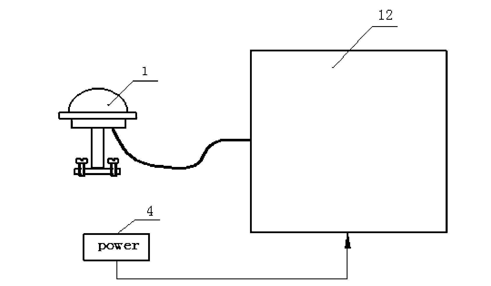
[0012] The present invention will be further described below in conjunction with accompanying drawing:

[0013] like figure 2 As shown, the present invention is based on a GPS signal source time unified signal generating device, which is composed of a GPS antenna 1 , a power module 4 and an integrated signal processing circuit board 12 .

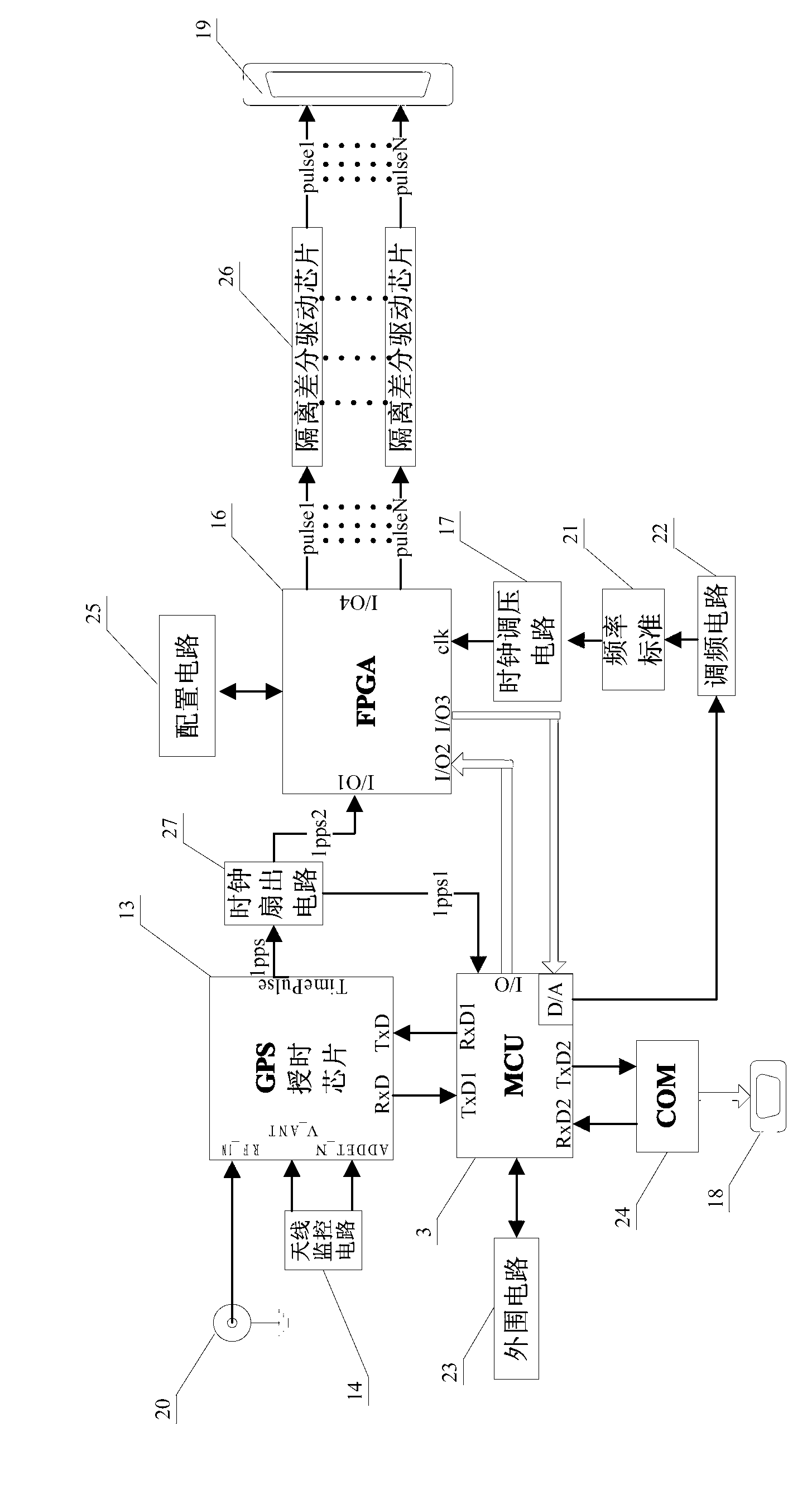
[0014] like image 3 As shown, the integrated signal processing circuit board 12 includes the following components, the model of the high-precision GPS timing chip 13 is LEA series (LEA-4T or LEA-5T), and the antenna monitoring circuit 14 can be composed of electronic components such as RLC according to actual conditions. Composition, mixed signal processing MCU (MCU) 15 chooses MSP430 series chip, digital logic circuit (FPGA) 16 chooses EP3C25 chip, clock (clk) voltage regulating circuit 17 is composed of MAX9013 chip and its auxiliary components, communication connector 18, synchronization Pulse signal output interface connector 19, rad...


PUM


Abstract

The invention discloses a time unification signal generating device based on a GPS (Global Position System) signal source, which belongs to the technical field of photoelectric measurement and control and overcomes the reliability risk caused by a dissipative structure of the traditional time unification device and the defects of external dependence in technology and maintenance caused by an outsourcing GPS receiver. The time unification signal generating device based on the GPS signal source is composed of a GPS antenna, a power supply module and an integrated signal processing circuit board, wherein the integrated signal processing circuit board comprises a GPS time service chip, an antenna monitoring circuit, an MCU (Micro Controller Unit), an FPGA (Field Programmable Gate Array), a clock voltage regulating circuit, a communication connector, an output interface connector, a radio-frequency signal input connector, a frequency standard, a frequency modulation circuit, a peripheral circuit, a serial communication circuit, a configuration circuit, an isolation difference drive chip and a clock fan-out circuit. The functions of a GPS receiving device and a synchronous signal generating device are integrated together by the integrated signal processing circuit board, thus the physical connection between inner signals of a system is reduced, the electromagnetic interference and the connection risk are avoided, and the reliability of the system is increased.

Description

technical field [0001] The invention relates to a time unification signal generating device based on a GPS signal source (abbreviation: a time unification device), which belongs to the technical field of photoelectric measurement and control. Background technique [0002] The timing device is widely used in various types of photoelectric measurement and control equipment. Its function is to provide standard time signals and frequency signals for the photoelectric measurement and control equipment, and its function is to realize the time and frequency between the measurement and control components on the photoelectric measurement and control equipment. It is an important device for photoelectric measurement and control equipment to ensure that the measurement and control steps of each measurement and control component on the optical measurement equipment are synchronized and the measurement results are accurate in real time. [0003] like figure 1 As shown, the known time sy...

Claims


Application Information

Patent Timeline
Patent Type & Authority Patents(China)
IPC IPC(8): G01S19/30
Inventor 王丽秋
Owner CHANGCHUN INST OF OPTICS FINE MECHANICS & PHYSICS CHINESE ACAD OF SCI
Why Eureka
Try Eureka