
Continuous evaporator

An evaporator, horizontal technology, applied in the field of once-through evaporation, can solve problems such as technical complexity, achieve the effects of improving flow distribution, reducing mechanical stress, and saving costs

Inactive Publication Date: 2012-09-12
SIEMENS AG
View PDF6 Cites 2 Cited by
  • Summary
  • Abstract
  • Description
  • Claims
  • Application Information

AI Technical Summary

Problems solved by technology

However, in horizontal waste heat boilers this measure may be technically complex

Method used


Image

  • Continuous evaporator
  • Continuous evaporator
  • Continuous evaporator

Examples


Embodiment Construction

[0024] The same reference numerals are used for the same parts in all figures.

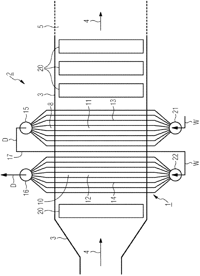
[0025] according to figure 1 The once-through evaporator 1 for the waste heat boiler 2 is connected downstream of the gas turbine, not shown in detail, with respect to the exhaust gas. The waste heat boiler 2 has a surrounding wall 3, which forms a gas channel 5 for the exhaust gas from the gas turbine, which can flow in a generally horizontal gas direction indicated by arrow 4. In the gas passage 5, some evaporator heating surfaces 8, 10 designed according to the principle of direct flow are arranged. in press figure 1 In the embodiment shown two evaporator heating surfaces 8, 10 are shown, but a larger number of evaporator heating surfaces can also be configured.

[0026] according to figure 1 The heating surfaces 8 and 10 of the evaporators respectively comprise some tube rows 11 or 12 arranged one behind the other along the gas direction in the form of tube bundles. Each tube row 11 or 12...


PUM


Abstract

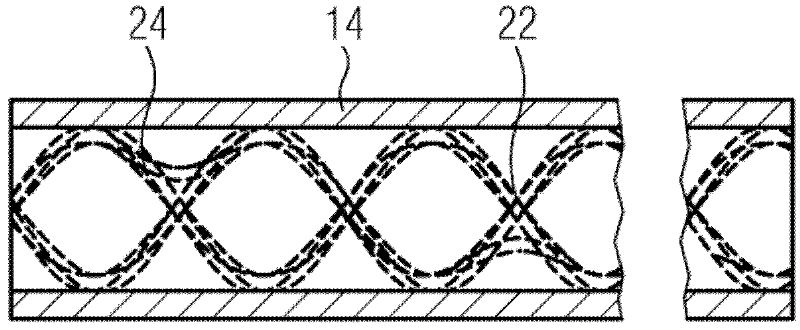
The invention relates to a continuous evaporator (1) for a horizontal waste heat steam generator comprising a first evaporator heating surface (8) that has a number of essentially vertically arranged first steam generating tubes (13) wherein the circulation takes place from the bottom to the top, and another second evaporator heating surface (10) located downstream of the first evaporator heating surface on the side of the flow medium, said second evaporator heating surface comprising a number of other essentially vertically arranged second steam generating tubes wherein the circulation takes place from the bottom to the top. The aim of the invention is to provide said continuous evaporator with an especially simple structure and an especially long service life. To this end, a number of second steam generating tubes (14) have an inner profiled element (22).

Description

technical field [0001] The invention relates to a once-through evaporator for a horizontal waste heat boiler, comprising a first evaporator heating surface, which has some first boiler tubes arranged substantially vertically and flowing from bottom to top, and including another For the flow medium, the second evaporator heating surface connected downstream of the first evaporator heating surface has other second boiler tubes arranged substantially vertically and flowing from bottom to top. Background technique [0002] In gas and steam turbine installations, the heat contained in the expanded working fluid or gas from the gas turbine is used to generate steam for the steam turbine. The heat is transferred into a waste heat boiler connected downstream of the gas turbine, which usually has heating surfaces for water preheating, steam generation and steam superheating. The heating surface is connected in the water-steam circuit of the steam turbine. The water vapor cycle usua...

Claims


Application Information

Patent Timeline
Patent Type & Authority Applications(China)
IPC IPC(8): F22B1/18F22B29/06F22B37/10
CPCF22B1/1815F22B29/062F22B37/103F28F1/40F25B39/02
Inventor J.布吕克纳J.弗兰克
Owner SIEMENS AG
Learn More