

Converter
A technology of converters and switching units, applied in the direction of instruments, high-efficiency power electronic conversion, output power conversion devices, etc., can solve the problem of voltage drop of the inductor 906, and achieve the effect of simplifying the structure
- Summary
- Abstract
- Description
- Claims
- Application Information
AI Technical Summary
Method used
Image

Examples
no. 1 Embodiment approach
[0068] (the whole frame)
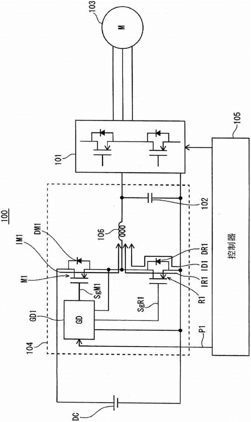
[0069] figure 1 An overall configuration diagram of a load drive system 100 including the converter according to the first embodiment is shown. In this embodiment, a configuration in which a three-phase AC motor is used as a load will be described.
[0070] The load drive system 100 includes a direct current power supply DC, a step-down converter 104 , an inverter 101 , a three-phase AC motor 103 , and a controller 105 .
[0071] The direct current power supply DC is, for example, a direct current power supply obtained by rectifying a power supply system, or a direct current power supply of a battery type (typically, a secondary battery such as nickel metal hydride or lithium ion).
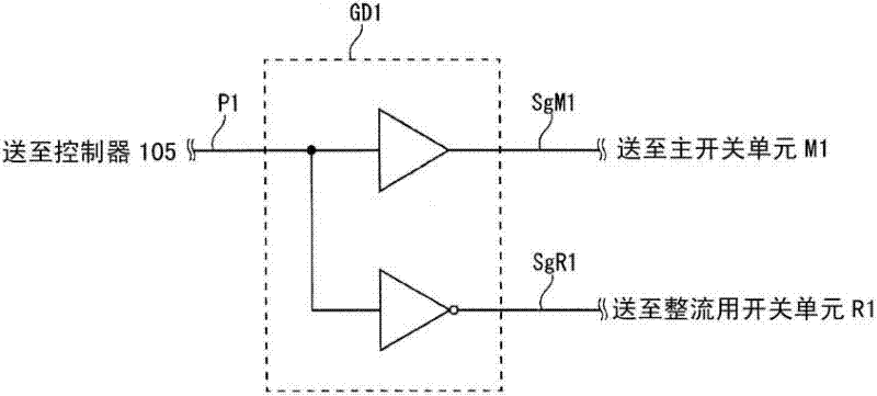
[0072] The step-down converter 104 steps down the voltage of the direct current power source DC, and outputs the reduced direct current voltage to the inverter 101 . Specifically, the step-down converter 104 includes a main switch unit M1, a rectification switch unit...
no. 2 Embodiment approach
[0146] Hereinafter, the second embodiment will mainly be described about the parts different from the first embodiment. In addition, since the timing chart in this embodiment and the Figure 4 are the same, so descriptions are omitted.
[0147] (the whole frame)
[0148] Figure 9 An overall configuration diagram of a load drive system 200 including a step-down converter according to the second embodiment is shown. The difference from the load drive system 100 according to the first embodiment is the configuration of the step-down converter 204 , particularly the configurations of the switching units M2 and R2 . In addition, for the same structure as the load driving system 100 attached to figure 1 same symbols, and their descriptions are omitted.
[0149] The step-down converter 204 is formed by connecting the main switch unit M2 and the rectification switch unit R2 in series. The gate drive circuit GD2 generates gate drive signals SgM1 , SgR1 for the main switching un...
no. 3 Embodiment approach
[0203] In this embodiment, a description will be given of a gate drive circuit configured to make it less likely that a short-circuit current will flow between switching cells.
[0204] Figure 23 (a) is a diagram showing the circuit configuration of the gate drive circuit according to the present embodiment, Figure 23 (b) is a graph showing the voltage fluctuation between the terminals of the switching unit during the switching operation. Furthermore, for Figure 23 The structure in (a), attached to the figure 1 The symbols shown in . Hereinafter, only the main switch unit will be described, but the rectification switch unit can also be described in the same way.
[0205] First, refer to Figure 23 (a) and (b), focusing on the gate capacitance (hereinafter, simply referred to as the gate capacitance of each switching unit) between the gate electrode and the source electrode of each switching unit for the switching operation performed by the switching unit. Charge and ...
PUM
| Property | Measurement | Unit |
|---|---|---|
| Thickness | aaaaa | aaaaa |
| Thickness | aaaaa | aaaaa |
| Thickness | aaaaa | aaaaa |
Abstract
Description
Claims
Application Information