Main power house for side-position arranged turbine generator

A technology for turbo generators and main workshops, applied in industrial buildings, etc., can solve the problems of shortening the length of high-temperature piping systems, reducing engineering investment, and high investment, and achieves the goals of improving normal operation efficiency, reducing engineering investment, and improving investment returns Effect

Active Publication Date: 2015-01-21
CHINA POWER ENG CONSULTING GRP CORP EAST CHINA ELECTRIC POWER DESIGN INST
View PDF2 Cites 0 Cited by
  • Summary
  • Abstract
  • Description
  • Claims
  • Application Information

AI Technical Summary

Problems solved by technology

[0005] In view of the above-mentioned shortcomings of the prior art, the side-positioned steam turbine-generator main plant building of the present invention has a large distance between the steam-turbine-generator and the boiler for the conventional front-position layout, which results in a long distance between the high-temperature interface between the steam turbine and the boiler, and a relatively small pipe system. Long, high investment, large flow resistance and low efficiency, all or part of the turbogenerator shafting is arranged on the left or right side of the boiler, thereby greatly shortening the length of the high-temperature piping system, significantly reducing the engineering investment, and reducing the system flow resistance, improve normal operating efficiency, and thus have a better return on investment

Method used


Image

  • Main power house for side-position arranged turbine generator
  • Main power house for side-position arranged turbine generator
  • Main power house for side-position arranged turbine generator

Examples


Embodiment Construction

[0027] Embodiments of the present invention will now be described in detail with reference to the accompanying drawings.

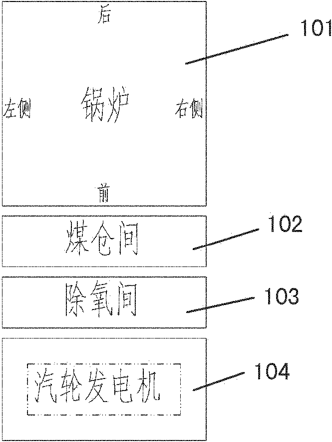
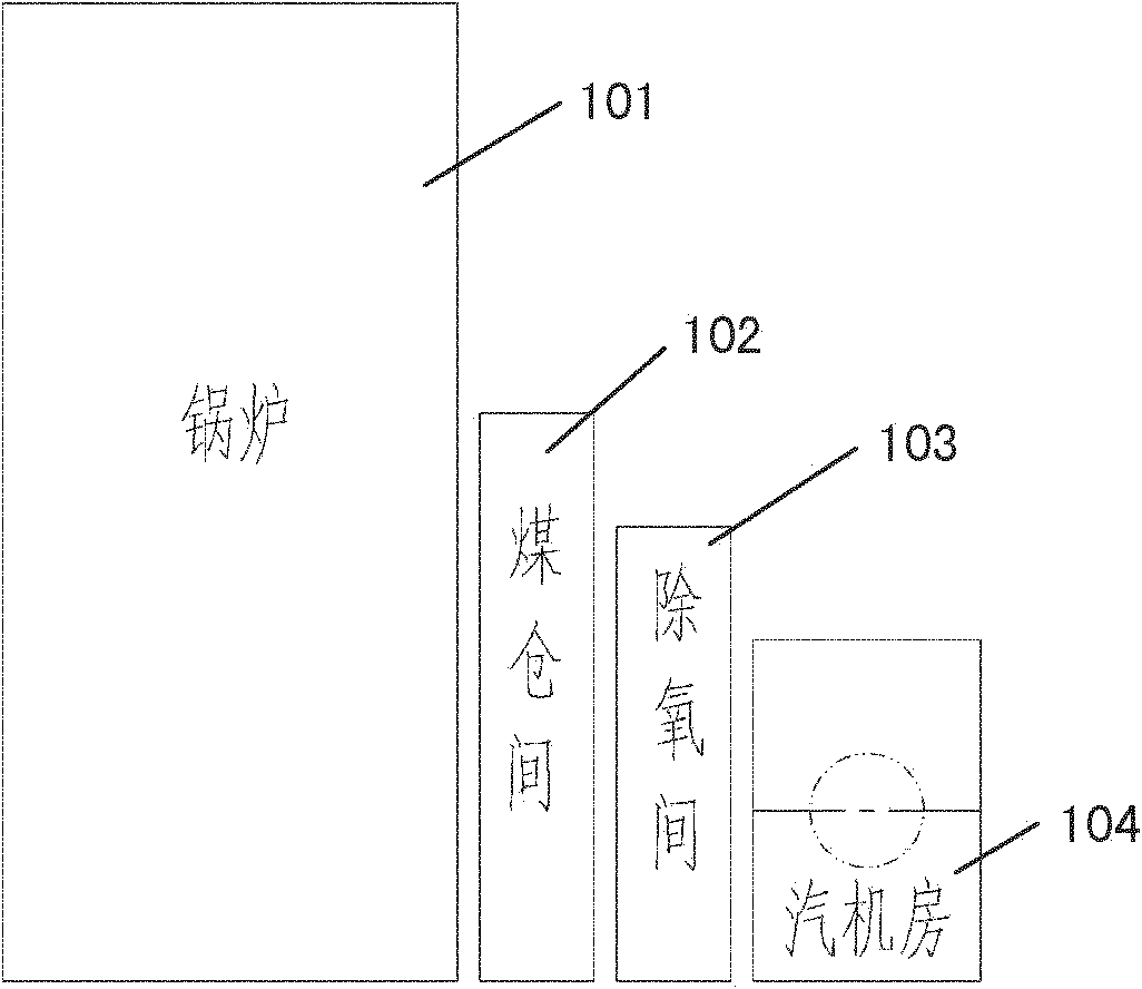
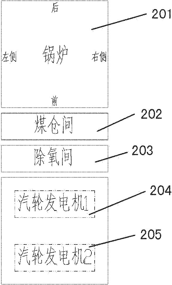
[0028] Aiming at the problems of long distance between the high temperature interface between the steam turbine and the boiler, long piping system, high investment, large flow resistance and low efficiency caused by the large distance between the steam turbine and the boiler in the conventional front position arrangement in the prior art, the present invention proposes a This is the main powerhouse with the steam turbine generator room arranged sideways. The main workshop includes a boiler room, a coal bunker room, a deoxygenation room and at least one turbogenerator room, wherein one of the at least one turbogenerator room is arranged adjacent to one side of the boiler room.

[0029] According to one aspect of the present invention, the above-mentioned at least one steam turbine generator room is a single-shaft turbo-generator machine room, wherein the si...


PUM


Abstract

The invention discloses a main power house for a side-position arranged turbine generator, which at least comprises a boiler house, a bunker room, a deoxidizing room and at least one turbine generator machine room. One of the turbine generator machine rooms is adjacent to one side of the boiler house. With the adoption of the main power house for the side-position arranged turbine generator, the length of the high-temperature pipe is greatly shortened, the engineering investment is obviously reduced and the normal operation efficiency is improved.

Description

technical field [0001] The invention relates to the field of electric power generation, in particular to a design of a main building of a steam turbine power plant arranged sideways. Background technique [0002] The common composition scheme of the main building of the turbogenerator in the prior art is as follows: Figure 1a , Figure 1b , Figure 2a and Figure 2b shown. Figure 1a and Figure 1b It is the most common single-shaft turbogenerator main building. Such as Figure 1a and Figure 1b As shown, in a conventional thermal power plant, the main building usually consists of 4 rows of turbine room, deaeration room, coal bunker room, and boiler room, and the turbine generator is arranged in the turbine room in front of the furnace. in particular, Figure 1a and Figure 1b In , the single-shaft turbogenerator is arranged in front of the furnace. Figure 2a and Figure 2b It is a common twin-shaft turbo-generator main workshop, which consists of 4 rows of turbine...

Claims


Application Information

Patent Timeline
Patent Type & Authority Patents(China)
IPC IPC(8): E04H5/02
Inventor 申松林林磊叶勇健陈仁杰施刚夜
Owner CHINA POWER ENG CONSULTING GRP CORP EAST CHINA ELECTRIC POWER DESIGN INST
Why Eureka
Try Eureka