Cam based on flexible engine oil injection

An engine and cam technology, used in engine components, machines/engines, mechanical equipment, etc., can solve the requirements that cannot take into account the requirements of injection pressure, injection rate and injection timing, and can not meet the requirements of emission regulations and economy. problems such as low injection pressure in the oil system, to achieve the effect of reducing noise and pollutant emissions, reducing emissions, and increasing fuel injection pressure

Inactive Publication Date: 2012-09-19
HARBIN ENG UNIV
View PDF6 Cites 0 Cited by
  • Summary
  • Abstract
  • Description
  • Claims
  • Application Information

AI Technical Summary

Problems solved by technology

Although the constant velocity cam has been widely used in the actual fuel injection system and has the advantage of being easy to control the injection law, it also has disadvantages: the constant velocity cam profile cannot take into account the influence of the injection pressure, injection pressure, and Injection rate and injection timing requirements, and the engine is in low-speed conditions, especially low-speed high-load conditions, the injection pressure of the fuel injection system is low, resulting in poor spray atomization effect, after the fuel enters the combustion chamber, The combustion of large particles of oil droplets creates local high temperature, which produces more pollutants during the combustion process, which cannot meet the requirements of emission regulations and economy

Method used


Image

  • Cam based on flexible engine oil injection
  • Cam based on flexible engine oil injection
  • Cam based on flexible engine oil injection

Examples


Embodiment Construction

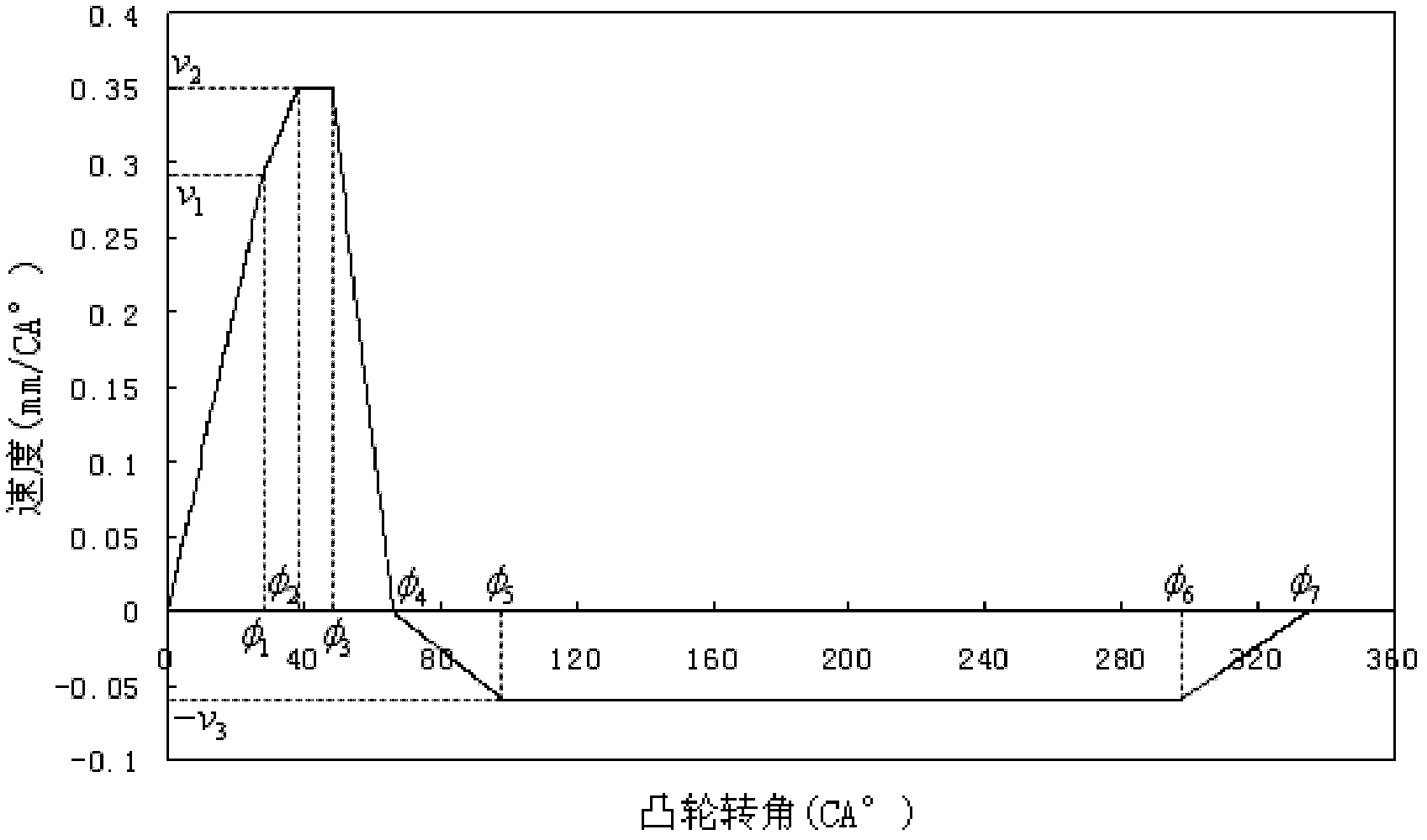
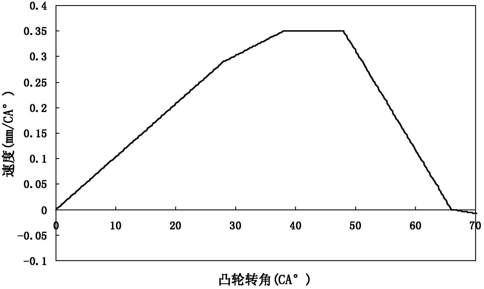
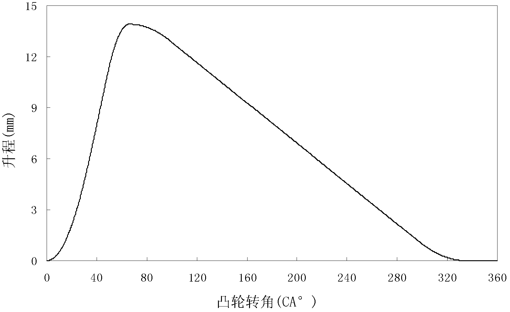
[0038] The present invention is described in more detail below in conjunction with accompanying drawing example:

[0039] With reference to Figures 1 to 3, the profile of the flexible fuel injection cam of the present invention has a thrust section corresponding to the forward constant acceleration stage of the movement law of the plunger follower [0°, φ 1 ], working section [φ 1 , φ 3 ] and the forward and other deceleration stages [φ 3 , φ 4 ], the return section of the cam corresponds to the reverse constant acceleration stage of the plunger follower motion law [φ 4 , φ 5 ], reverse constant velocity stage [φ 5 , φ 6 ] (rate size is v 3 ) and deceleration stages such as reverse [φ 6 , φ 7 ]. The cam working section also includes the acceleration stage [φ 1 , φ 2 ] (initial rate is v 1 ) and forward constant velocity stage [φ 2 , φ 3 ] (rate size is v 2 ). The equations of motion for each segment of the plunger follower are:

[0040] 1. Forward constant acc...


PUM


Abstract

The invention aims to provide a cam based on flexible engine oil injection. The cam comprises a rise travel section and a return section, wherein the rise travel section corresponds to a positive equally accelerating stage, a working section and a positive equally decelerating stage of a motion rule of an engine plunger driven piece; the return section corresponds to a reverse equally accelerating stage, a reverse constant speed stage and a reverse equally decelerating stage of the motion rule of the engine plunger driven piece; the reverse constant speed stage has the rate of v3; and the working section comprises an accelerating stage and a positive constant speed stage, wherein the accelerating stage has the initial rate of v1, and the positive constant speed stage has the rate of v2. The cam has the advantages that the requirements of oil injection pressure, oil injection speed and oil injection timing of a diesel engine at high/low rotary speed can be met, the oil injection flexibility under high-rotary speed working conditions can be improved, and the oil injection pressure under low-rotary speed working conditions is increased.

Description

technical field [0001] The present invention relates to cams in the field of engines. Background technique [0002] In the traditional technology, the fuel supply pump cam used in the electronic control fuel injection system of diesel engine is a constant velocity cam, and its thrust section corresponds to the positive constant acceleration, forward constant velocity and forward constant deceleration stages of the plunger follower movement law, and the return stroke The segment corresponds to the reverse constant acceleration, reverse constant velocity and reverse deceleration stages of the motion law of the cam plunger follower. Although the constant velocity cam has been widely used in the actual fuel injection system and has the advantage of being easy to control the injection law, it also has disadvantages: the constant velocity cam profile cannot take into account the influence of the injection pressure, injection pressure, and Injection rate and injection timing requi...

Claims


Application Information

Patent Timeline
Patent Type & Authority Applications(China)
IPC IPC(8): F02M51/04
Inventor 范立云王昊白云田丙奇马修真宋恩哲李文辉石勇袁志国
Owner HARBIN ENG UNIV
Why Eureka
Try Eureka