Compound furnace arch and compound secondary air structure for cooperatively controlling generation of nitrogen oxide (NOX)

A nitrogen oxides, collaborative control technology, applied in lighting and heating equipment, non-flammable liquid/gas transportation, combustion methods, etc., can solve the problems of low removal efficiency, lack of active control, high operating costs, and achieve NOX The reduction reaction is sufficient, the mixing is strengthened, and the effect of avoiding premature mixed combustion

Active Publication Date: 2012-09-19
XI AN JIAOTONG UNIV
View PDF4 Cites 6 Cited by
  • Summary
  • Abstract
  • Description
  • Claims
  • Application Information

AI Technical Summary

Problems solved by technology

This traditional furnace arch structure can significantly improve the combustion efficiency of the boiler, but because it highlights the importance of ignition and enhanced combustion, it ignores the source of NO produced during the combustion process. X Active control technology research and development, lack of active control NO X Generated relevant structural design technology, and for industrial boilers, if the NO can not be actively controlled X generation, we can only use ammonia injection technology on the upper part of the furnace or implement SCR flue gas denitrification post-treatment technology, etc., while ammonia injection removes NO X Although the technology is simple, the removal efficiency is low, ammonia, urea and other substances are consumed all the time, and the operating cost is high
As for SCR, not only ammonia injection, but also the use of expensive catalysts to accelerate the removal reaction, the operating cost is higher

Method used


Image

  • Compound furnace arch and compound secondary air structure for cooperatively controlling generation of nitrogen oxide (NOX)
  • Compound furnace arch and compound secondary air structure for cooperatively controlling generation of nitrogen oxide (NOX)
  • Compound furnace arch and compound secondary air structure for cooperatively controlling generation of nitrogen oxide (NOX)

Examples


Embodiment Construction

[0023] The structure of the present invention will be further described in detail below in conjunction with the accompanying drawings and specific embodiments.

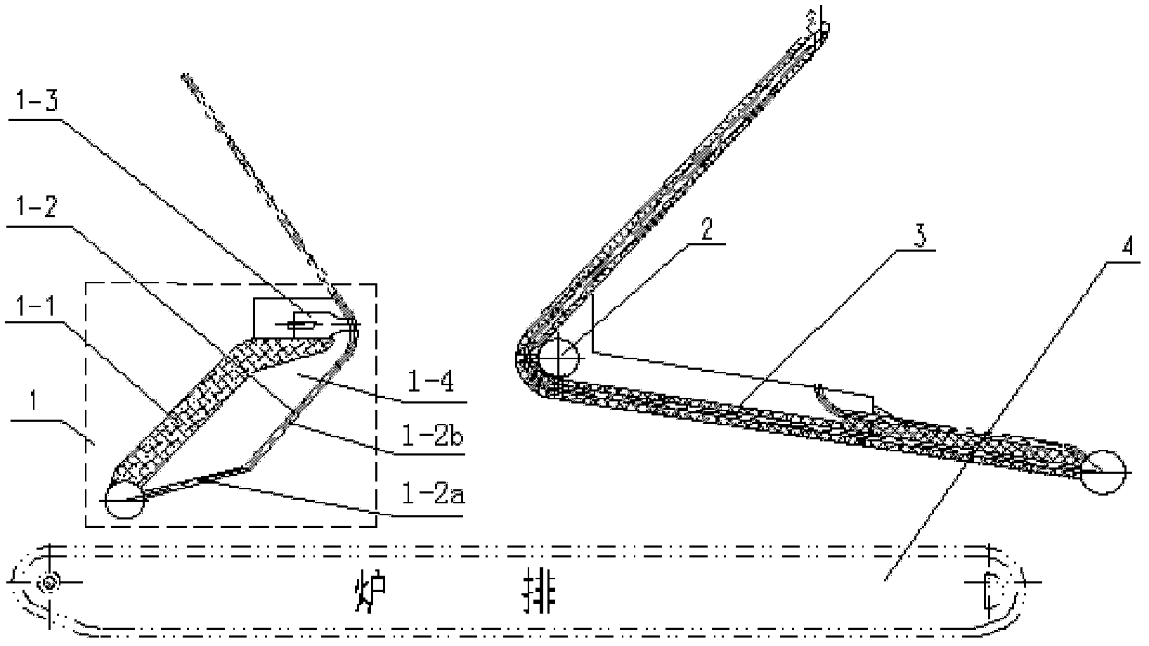
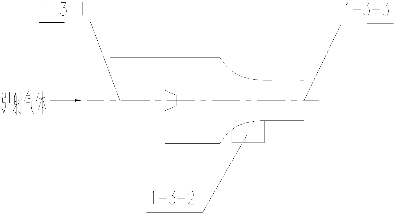
[0024] Such as figure 1 As shown, the present invention is a composite furnace arch and composite secondary air structure that synergistically controls the formation of nitrogen oxides, including a front arch 1 and a rear arch 3, and the water-cooled wall 1-2 of the front arch 1 protrudes toward the interior of the furnace so that A cavity 1-4 is formed between it and the front arch furnace wall 1-1, and an ejector 1-3 is equipped with at the top outlet of the cavity 1-4. The front arch furnace wall 1-1 is made of refractory material, the lower part 1-2a of the water-cooled wall 1-2 adopts a smooth tube water-cooled wall, leaving gaps between the tube bundles, and the upper part 1-2b adopts a membrane-type water-cooled wall, The reducing volatile gas generated by pyrolysis can enter the cavity 1-4 from the lower part...


PUM


Abstract

The invention relates to a compound furnace arch and a compound secondary air structure for cooperatively controlling generation of an NOX. A front arch water cooled furnace wall protrudes into a furnace to form a cavity with a fire-resistant front arch, an ejector is arranged at the throat portion of the front arch to eject volatiles, a compound secondary air device is arranged at the throat portion of a rear arch, and a nozzle of the ejector and a rear arch secondary air horizontal nozzle are arranged at an interval horizontally and oppositely. Compared with the prior art, according to the compound furnace arch and the compound secondary air structure for cooperatively controlling generation of nitrogen oxides, the volatiles are drawn out from the cavity between the front arch furnace wall and the front arch water cooled furnace wall and reacted with the NOX in high temperature flue gas, simultaneously high temperature ammonia jetting can be achieved during deep removal of NOX, so that technology integration of actively and cooperatively removing the NOX of stage combustion of fuels of the compound front arch and the ejector, stage combustion of compound secondary air and volatile re-burning is achieved, NOX emission levels of chain grate furnaces or grate-fired furnaces using similar principles are obviously reduced, and standard emission of the NOX of industrial grate-fired furnaces is achieved.

Description

technical field [0001] The invention belongs to the technical field of controlling nitrogen oxide emissions of a layer-fired boiler, and in particular relates to a composite furnace arch and composite secondary air structure for synergistically controlling the generation of nitrogen oxides. Background technique [0002] Since 2000, with the development of my country's industrialization and urbanization, the improvement of energy conservation and environmental protection requirements, and the huge increase in urban heating demand, large-capacity layer-fired coal-fired central heating boilers have entered a period of rapid development. Among the coal-fired industrial boilers in my country, the layer-fired chain boilers account for more than 60% of the total number of industrial boilers. Therefore, the energy saving and emission reduction of chain boilers is the top priority of energy saving and emission reduction of industrial boilers in my country. In the design and operatio...

Claims


Application Information

Patent Timeline
Patent Type & Authority Applications(China)
IPC IPC(8): F23M5/06F23L9/00
Inventor 赵钦新张吉虎李钰鑫王云刚
Owner XI AN JIAOTONG UNIV
Why Eureka
Try Eureka