Vortex self-cleaning energy-saving pipe

A vortex and spiral technology, applied in the field of condenser tubes, can solve the problems of increasing the difficulty of cleaning, complex manufacturing, and damage to the boundary layer, etc., to enhance the convective heat transfer and condensation heat release coefficient, enhance the mechanical strength and anti-vibration performance, The effect of preventing the generation of dirt

Inactive Publication Date: 2012-09-19
董斌
View PDF4 Cites 3 Cited by
  • Summary
  • Abstract
  • Description
  • Claims
  • Application Information

AI Technical Summary

Problems solved by technology

[0004] When the spiral groove heat exchange tube is used, although there is a swirling effect at low speed, because the spiral protrusion is continuous, it cannot form a stripping point that can erode the dirt, and the swirling flow at low speed will cause dirt to adhere. The elimination of the laminar flow bottom layer (boundary layer) is not complete, and the problem of dirt adhesion at low flow rates cannot be solved, so the spiral grooved tube cannot meet our pursuit of self-cleaning and anti-fouling effects
[0005] For spinous tubes with rough element characteristics, such as spherical concave-convex heat exchange tube [96235149.0], although it has the characteristics of sand-type rough elements, if the rough element height is too high, it will greatly increase the

Method used


Image

  • Vortex self-cleaning energy-saving pipe
  • Vortex self-cleaning energy-saving pipe
  • Vortex self-cleaning energy-saving pipe

Examples


Embodiment Construction

[0016] Below in conjunction with accompanying drawing, the present invention is described as follows:

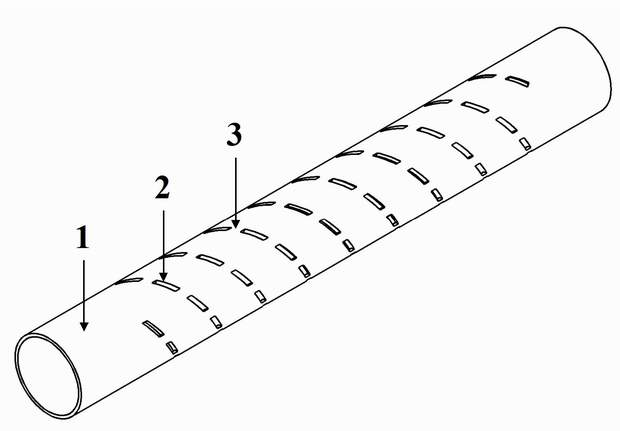
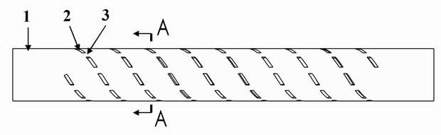
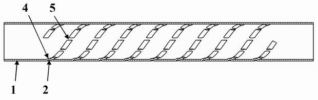
[0017] The constituent elements of the vortex cleaning tube of the present invention are: tube body 1, outer wall surface groove 2, outer wall surface groove gap 3, inner wall surface protrusion 4, inner wall surface protrusion gap 5; outer wall surface groove 2 is spiral along the outer wall of the tube The lines are distributed on the outer wall of the tube, and there is a gap 3 between the grooves; the inner wall has protrusions 4 corresponding to the grooves on the outer wall, so the protrusions 4 are distributed in a spiral shape along the inner wall of the tube, and there are gaps between the inner wall protrusions. Gap 5, see attached Figure 1-7 As shown, the number of heads of the spiral can be single head, double head, three heads, four heads, five heads, and six heads. Figure 4 Where p is the pitch between adjacent helices, the pitch p between the helices is equ...


PUM

PropertyMeasurementUnit
Helix angleaaaaaaaaaa

Abstract

The invention discloses a vortex self-cleaning energy-saving pipe. The cyclone disturbance characteristic of a spiral grooved pipe, the eddy current disturbance characteristic of a rough element and the tension damage characteristics of a porous surface are organically combined and the erosion action of the fluid is fully utilized, erosion points which facilitate the removal of dirt on the pipe wall of a heat exchange pipe are artificially created, rotating eddy current is formed at the erosion points and the erosion action of the fluid is allowed to expand from the points to the surface until the whole pipe wall, and thus the functions of eliminating a boundary layer, enabling the heat exchange pipe to keep self-clean for a long term and generating an effect of removing the dirt are achieved. According to the vortex self-cleaning energy-saving pipe, the boundary layer between the fluid and the pipe wall, which is a chief reason for forming the dirt and influencing heat exchange, is effectively removed by combining cyclone with the flowing characteristic of the rough element, and further the dirt is prevented from the source; a surface groove with a clearance has the characteristic of the porous surface, so that a condensed water film influencing condensation heat exchange can be effectively damaged, low-efficiency film type condensation is changed into high-efficiency dropwise condensation and convection heat exchange and condensing heat emission coefficients are greatly enhanced. Therefore, the vortex self-cleaning energy-saving pipe has the characteristics of high heat exchange efficiency, and self-cleaning capability for dirt removal and dirt prevention.

Description

technical field [0001] The invention relates to a condenser pipe used in tubular heat exchangers such as condensers. It is also called a clean energy pipe because it has the effects of self-cleaning, anti-fouling and energy saving. It is used for steam turbines widely used in thermal power generation, steel, petroleum and chemical fields. Tube heat exchangers such as condensers belong to the field of heat exchange. Background technique [0002] The development of heat exchange tubes has experienced the first generation of heat exchange technologies represented by light pipes and optical channels, the second generation of heat exchange technologies represented by planar fins, two-dimensional rough elements, two-dimensional ribs, etc., and the three-dimensional rough The third-generation heat exchange technology represented by three-dimensional micro-ribs, etc., and the fourth-generation heat exchange technology that strengthens the mechanical strength and vibration resistance...

Claims


Application Information

Patent Timeline
IPC IPC(8): F28F1/42
Inventor 董斌
Owner 董斌
Why Eureka
Try Eureka