
Piezoelectric biaxial micro gyroscope with rocking mass block

A quality block and micro-gyroscope technology, applied in the field of micro-gyroscopes, can solve the problems of driving and detection electrodes falling off, high cost, and limited use range, etc., and achieve the effects of increased reliability, easy processing, and simple structure

Inactive Publication Date: 2012-09-19
SHANGHAI JIAO TONG UNIV
View PDF10 Cites 8 Cited by
  • Summary
  • Abstract
  • Description
  • Claims
  • Application Information

AI Technical Summary

Problems solved by technology

[0004] This technology has the following disadvantages: firstly, the gyroscope with rocking mass is large in size, which limits its scope of use; secondly, the gyroscope is processed by mechanical technology and cannot be mass-produced, and the cost is high; finally, the most important aspect of this technology The disadvantage is that the driving and detecting electrodes are assembled on the support beam with the adhesive chip process. When working at high frequency resonance, the driving and detecting electrodes are prone to fall off, which affects the reliability of the micro gyroscope.

Method used


Image

  • Piezoelectric biaxial micro gyroscope with rocking mass block
  • Piezoelectric biaxial micro gyroscope with rocking mass block
  • Piezoelectric biaxial micro gyroscope with rocking mass block

Examples


Embodiment Construction

[0026] Below in conjunction with accompanying drawing, the embodiment of the present invention is described in detail: present embodiment is carried out under the premise of technical solution of the present invention, has provided detailed implementation mode and specific operation process, but protection scope of the present invention is not limited to following the embodiment.

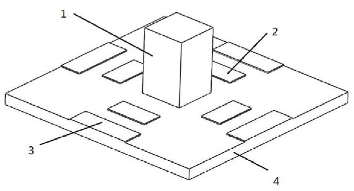
[0027] Such as figure 1 As shown, this embodiment includes a rocking mass resonator 1 , four driving electrodes 2 parallel to the substrate side, four detection moving electrodes 3 parallel to the substrate side, and a substrate 4 .

[0028] In this embodiment, the material of the substrate 4 is a PZT piezoelectric material, and only four sides of the substrate are fixed, and the rest of the substrate is not restricted by degrees of freedom.

[0029] In this embodiment, the material of the rocking mass resonator 1 is metal, and the shape is a cuboid. The substrate is an equilateral thin plate, and...


PUM


Abstract

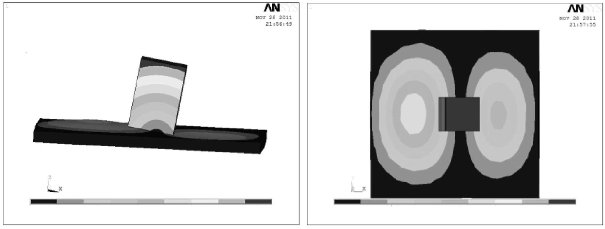
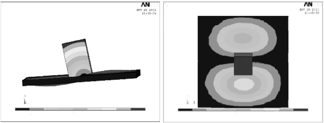
The invention relates to a piezoelectric biaxial micro gyroscope with a rocking mass block in the technical field of micro electro-mechanics. The micro gyroscope comprises a rocking mass block harmonic oscillator, a base plate for supporting the rocking mass block, four driving electrodes which are parallel to the edges of the base plate and are arranged at intervals, and four detection electrodes parallel to the edges of the base plate. Angular speeds in two directions in the base plate surface are detected by using the special vibration mode of the rocking mass block harmonic oscillator, adopting drive of the inverse piezoelectric effect and detecting the voltage change on the piezoelectric electrodes, and the input angular speeds in the two directions in the base plate surface are acquired through a peripheral mediation processing circuit. By adopting the fine machining technology of a micro-electromechanical system (MEMS), the micro gyroscope is simple in structure, and can realize biaxial direction; and the machining technology is easy to implement and high in reliability.

Description

technical field [0001] The present invention relates to a micro-gyroscope in the field of micro-electromechanical technology, in particular to a biaxial gyroscope that utilizes piezoelectricity to drive and detect, and uses a rocking mass as a resonant oscillator. Background technique [0002] Gyroscope is an inertial device that can be sensitive to the angle or angular velocity of the carrier, and it plays a very important role in the fields of attitude control, navigation and positioning. With the development of national defense technology and aviation and aerospace industries, the requirements of inertial navigation systems for gyroscopes are also developing in the direction of low cost, small size, high precision, multi-axis detection, high reliability, and adaptability to various harsh environments. The micro gyroscope based on MEMS technology is processed by micro-nano batch manufacturing technology, its cost, size, and power consumption are very low, and its environme...

Claims


Application Information

Patent Timeline
IPC IPC(8): G01C19/56
Inventor 张卫平许仲兴关冉张弓成宇翔陈文元吴校生刘武崔峰
Owner SHANGHAI JIAO TONG UNIV
Learn More