Digitalized optical fiber voltage transformer

A technology of voltage transformer and voltage sensor, which is applied in the direction of voltage/current isolation, etc., can solve the problems of no short circuit, overvoltage output, large secondary output power, etc., and achieves easy transportation and installation, simple insulation structure, and anti-interference ability strong effect

Inactive Publication Date: 2012-09-19
HUAZHONG UNIV OF SCI & TECH
View PDF8 Cites 8 Cited by
  • Summary
  • Abstract
  • Description
  • Claims
  • Application Information

AI Technical Summary

Problems solved by technology

Limited by the sensing mechanism, the traditional voltage transformer has a small dynamic range and a narrow frequency band, and has the disadvantages of being prone to ferromagnetic resonance and causing overvoltage and output cannot be short-circuited.
On the other hand, the output terminal of the traditional electromagnetic voltage transformer is directly connected to the vehicle-mounted device. When the primary winding of the transformer is discharged or the insulation breaks down, the high voltage may enter the secondary side and endanger the safety of personnel and instrumentation equipment.
The secondary output power of the traditional transformer is large, there is heat inside, and the failure rate is high

Method used


Image

  • Digitalized optical fiber voltage transformer
  • Digitalized optical fiber voltage transformer

Examples


example

[0017] Typical examples are as follows:

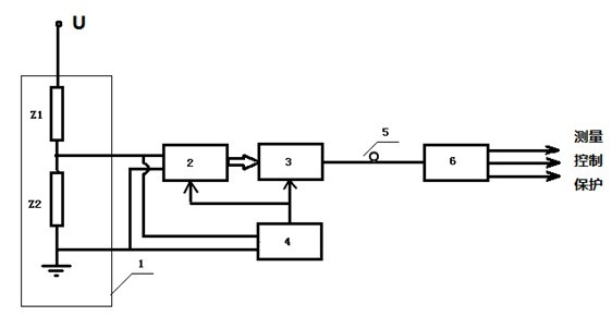
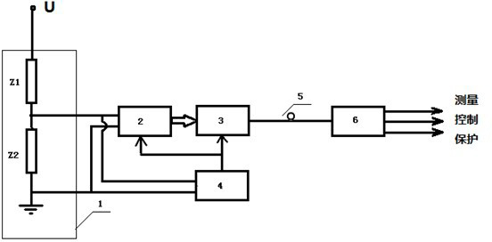
[0018] When the grid high voltage U=25kV, the voltage on the low-voltage impedance Z2 is 5V, which is the input voltage of the A / D converter 2, and the A / D converter 2 outputs the corresponding digital signal to the control processing unit 3, and the control processing The unit 3 outputs a serial digital optical signal through control and processing, and the optical signal is coupled into the communication optical fiber 5 for transmission, and the signal receiving unit 6 receives the optical signal transmitted by the optical fiber 5 and converts it into a required electrical signal for use by the vehicle-mounted device. The power source 4 provides a DC voltage source with an output of 5V after the energy obtained from Z2 in the voltage sensor 11 is rectified and stabilized for use by the A / D converter 2 and the control processing unit 3 .

[0019] The invention is completely designed in accordance with national standards and railway st...


PUM


Abstract

The invention discloses a digitalized optical fiber voltage transformer which comprises a voltage sensor positioned at the top of a vehicle, an A / D (Analog / Digital) converter, a control processing unit, a power supply module and a signal receiving unit positioned in the vehicle, wherein the control processing unit is connected with the signal receiving unit through a communication optical fiber; the voltage sensor is used for acquiring a signal from a power grid, is a voltage division type voltage sensor and is formed by connecting high-voltage impedance with low-voltage impedance in series; the A / D converter is connected with the low-voltage resistance in parallel; the input end of a power supply is connected with the low-voltage resistance in parallel; and the signal receiving unit receives an optical signal transmitted by the communication optical fiber and converts the optical signal into a voltage signal. According to the digitalized optical fiber voltage transformer disclosed by the invention, due to the adoption of the voltage division type voltage sensor, no external power supply and battery are needed; the output end of the digitalized optical fiber voltage transformer is in communicated connection with a vehicle-mounted device through an optical fiber, strong anti-jamming capability is obtained and complete electrical isolation can be realized. The digitalized optical fiber voltage transformer can replace an original traditional transformer for a locomotive and is especially suitable for electric locomotives (including urban rail locomotives).

Description

technical field [0001] The invention relates to electric locomotive network voltage measurement technology, in particular to a digital optical fiber voltage transformer, which is especially suitable for electric locomotives (including urban rail locomotives). technical background [0002] At present, electric locomotives mainly use traditional electromagnetic voltage transformers to measure the grid voltage. Limited by the sensing mechanism, the traditional voltage transformer has a small dynamic range and a narrow frequency band, and has the disadvantages of being prone to ferromagnetic resonance and causing overvoltage and output cannot be short-circuited. On the other hand, the output terminal of the traditional electromagnetic voltage transformer is directly connected to the vehicle-mounted device. When the primary winding of the transformer discharges or the insulation breaks down, high voltage may enter the secondary side and endanger the safety of personnel and instru...

Claims


Application Information

Patent Timeline
Patent Type & Authority Applications(China)
IPC IPC(8): G01R15/18
Inventor 徐雁张光群肖霞朱明钧徐垦孙文胡书红
Owner HUAZHONG UNIV OF SCI & TECH
Why Eureka
Try Eureka