Grid electrode driving circuit and display

A gate drive circuit and circuit technology, applied in static indicators, instruments, static memory, etc., can solve the problems of increasing gate drive circuit power consumption, low mobility of a-Si, increasing gate drive circuit space, etc. To achieve the effect of long service life and low power consumption

Active Publication Date: 2012-09-19
BOE TECH GRP CO LTD
View PDF4 Cites 66 Cited by
  • Summary
  • Abstract
  • Description
  • Claims
  • Application Information

AI Technical Summary

Problems solved by technology

[0009] Second, due to the low mobility of a-Si, in order to meet the higher on-state current (Ion) requirements of some TFTs in the circuit, it is necessary to incr

Method used


Image

  • Grid electrode driving circuit and display
  • Grid electrode driving circuit and display
  • Grid electrode driving circuit and display

Examples


Embodiment Construction

[0048] In order for those skilled in the art to better understand the technical solution of the present invention, the gate drive circuit and the display provided by the present invention will be described in detail below with reference to the accompanying drawings.

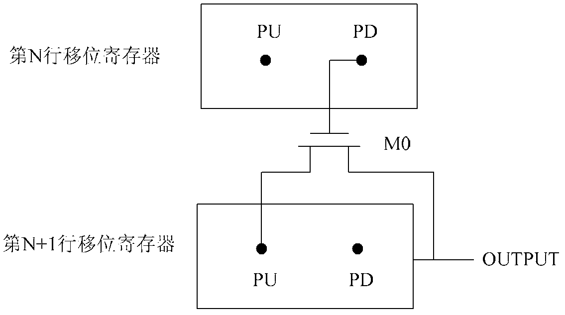
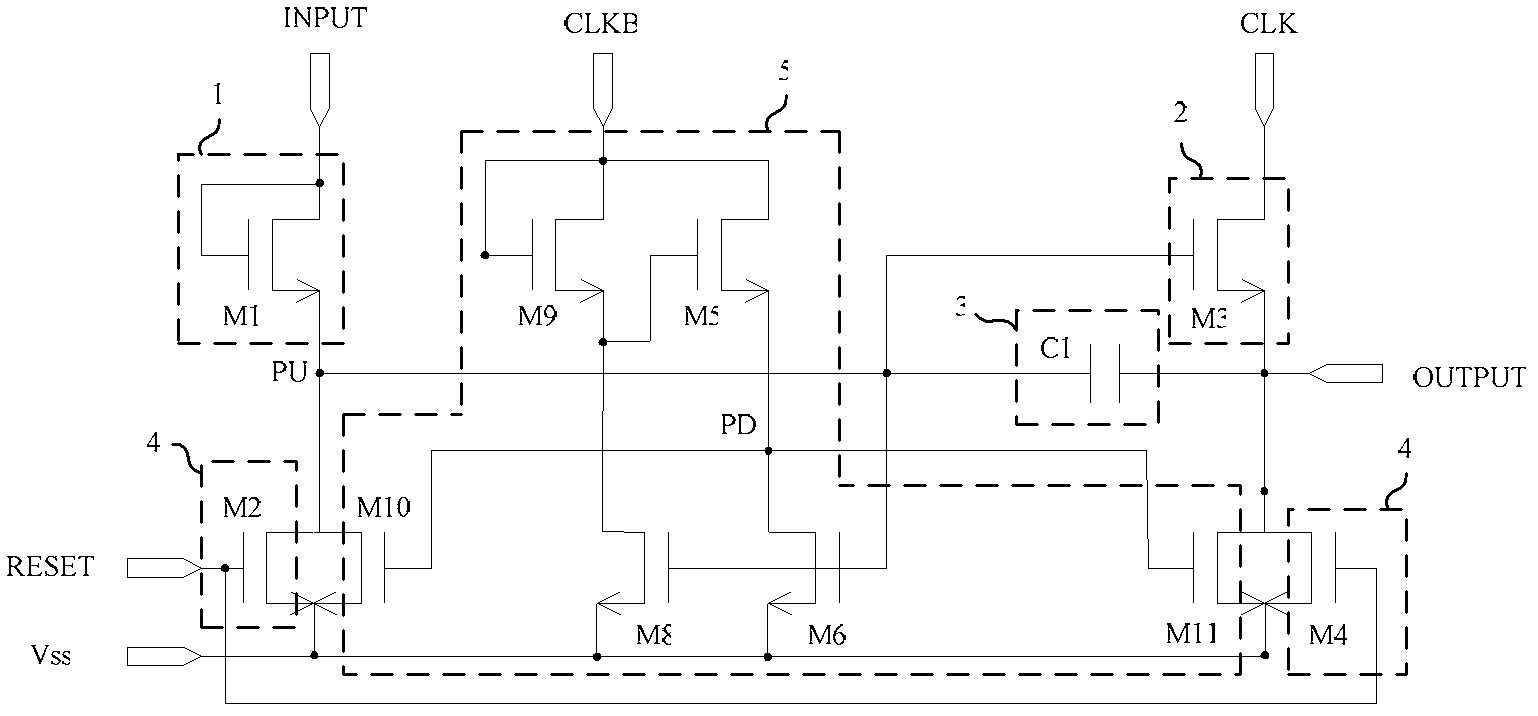
[0049] figure 1 A structural block diagram of a gate drive circuit provided by an embodiment of the present invention, figure 2 It is a schematic diagram of the gate driving circuit of the embodiment of the present invention. see figure 1 with figure 2 , the gate drive circuit provided in this embodiment includes a plurality of cascaded shift registers, and the shift registers include:

[0050] Signal input circuit 1, the signal input circuit 1 is used to receive the output signal INPUT of the previous shift register, and to turn on the signal output circuit.

[0051] Signal output circuit 2, the signal output circuit 2 is used to receive the first clock signal CLK from the external circuit, the output end ...


PUM


Abstract

The invention provides a grid electrode driving circuit and a display. The grid electrode driving circuit comprises multiple cascade-connected shift registers, wherein each shift register comprises a signal input circuit, a signal output circuit, an upward pulling circuit, a reset circuit and a downward pulling circuit; the signal input circuit, the signal output circuit, the upward pulling circuit and the reset circuit are converged to form a first node PU, the control end of the downward pulling circuit is a second node PD, an auxiliary transistor is also arranged between two adjacent shift registers, the grid electrode of the auxiliary transistor is connected with the second node PD of the shift register in the Nth line, the source electrode of the auxiliary transistor is connected with the first node PU of the shift register in the (N+1)th line, and the drain electrode of the auxiliary transistor is connected with the signal output circuit of the shift register in the (N+1)th line. The grid electrode driving circuit is low in power consumption and long in service life.

Description

technical field [0001] The invention belongs to the field of displays, and in particular relates to a gate drive circuit for a display and a display. Background technique [0002] The Gate-Driver on Array (Gate-Driver on Array, hereinafter referred to as GOA) process is to fabricate the gate drive circuit of the display on the glass substrate through the array process, so as to scan and drive the display area. [0003] Compared with the traditional process of fixing IC chips on flexible circuit boards (Chip on Film, hereinafter referred to as COF) and chips directly fixed on glass (Chip on Glass, hereinafter referred to as COG), the GOA process has the following advantages: [0004] First, the manufacturing cost of the gate drive circuit can be reduced; [0005] Second, since the gate integrated circuit (Gate IC) and the fan-out (Fan-out) wiring space are omitted, the design of the narrow frame can be realized, and the panel (Panel) can be designed symmetrically, so that M...

Claims


Application Information

Patent Timeline
IPC IPC(8): G09G3/32
CPCG09G3/36G09G3/3648G09G3/3681G11C19/28
Inventor 孙阳
Owner BOE TECH GRP CO LTD
Why Eureka
Try Eureka