Laser lift-off device

A laser peeling and laser technology, applied in laser welding equipment, electrical components, circuits, etc., can solve problems such as poor laser peeling treatment, and achieve the effect of effectively removing dust particles and inhibiting dust particles from flying

Inactive Publication Date: 2012-09-19
USHIO DENKI KK
View PDF2 Cites 17 Cited by
  • Summary
  • Abstract
  • Description
  • Claims
  • Application Information

AI Technical Summary

Problems solved by technology

This may cause poor laser lift-off processing

Method used


Image

  • Laser lift-off device
  • Laser lift-off device
  • Laser lift-off device

Examples


Embodiment Construction

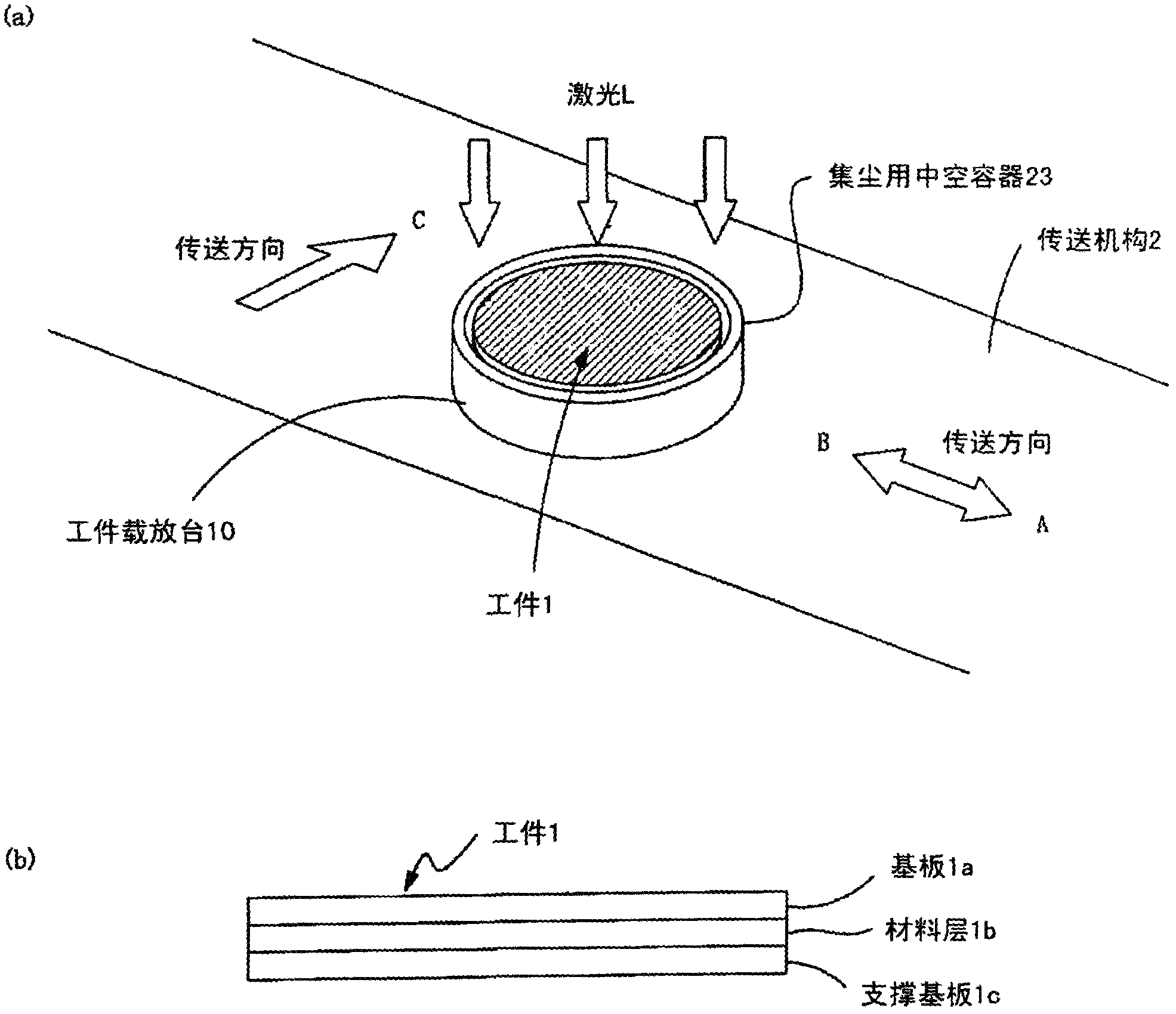
[0073] figure 1 It is a schematic diagram explaining the outline of the laser lift-off process of the Example of this invention.

[0074] In this embodiment, the laser lift-off process is performed as follows.

[0075] figure 1 (b) shows the workpiece 1 formed by stacking the laser-transmitting substrate 1a, the material layer 1b and the supporting substrate 1c, such as figure 1 As shown in (a), it is placed on the workpiece placement table 10 . The workpiece 1 is placed on the workpiece mounting table 10 so that the substrate 1 a is located above.

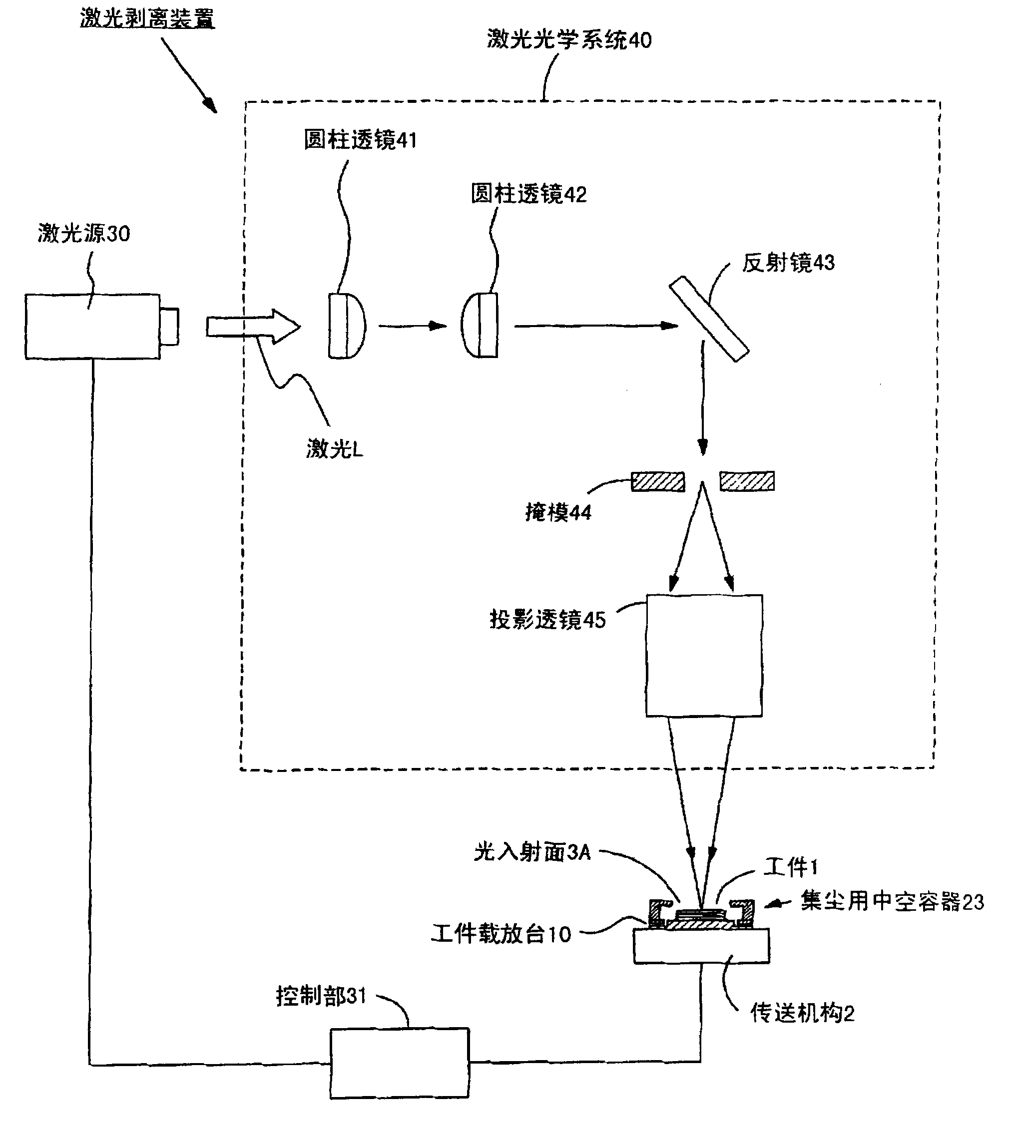
[0076] The workpiece table 10 on which the workpiece 1 is placed is placed on a conveying mechanism 2 such as a conveyor belt, and is conveyed at a predetermined speed by the conveying mechanism 2 . The workpiece 1 is transported in the arrow direction AB in the figure together with the workpiece stage 10 , and penetrates the substrate to be irradiated with pulsed laser light L emitted from a pulsed laser source not shown. ...


PUM


Abstract

A laser lift-off device eliminates baneful influence of various dust particles generated from a workpiece due to laser irradiation for the workpiece. A periphery of a carrier platform part (11) of a workpiece carrier platform (10) is provided with an annular wall part (21) consisting of an annular outer wall part (21b) and a top wall part (21a). The carrier platform part (11) is provided with outlets (12) used for connecting with exhaust mechanisms at a plurality of positions. The outlets (12) absorb the air in the annular wall part (21) through tubings connected with the exhaust mechanisms such as pumps, fans, and so on. By using the laser to radiate a workpiece (1), the dust particles ejected along with gas from an edge part of the workpiece (1) towards inner spaces (A) divided by the annular outer wall part (21b) and the top wall part (21a) are discharged from the outlets (12) provided on the carrier platform part (11) through flow of fluid towards the outlets (12).

Description

technical field [0001] The present invention relates to a laser lift-off method and a laser lift-off device for decomposing a material layer formed on a substrate by irradiating laser light to a material layer formed on a substrate in a manufacturing process of a semiconductor light-emitting element formed of a compound semiconductor, thereby peeling off the substrate (hereinafter referred to as laser lift-off). Background technique [0002] In the manufacturing process of a semiconductor light-emitting device formed of a GaN (gallium nitride)-based compound semiconductor, laser light is known to peel off a GaN-based compound material layer (material layer) formed on a sapphire substrate by irradiating laser light from the back surface of the sapphire substrate. Stripping technique. Hereinafter, the process of irradiating a material layer formed on a substrate with laser light to peel the material layer from the substrate is referred to as laser lift-off. [0003] For exam...

Claims


Application Information

Patent Timeline
Patent Type & Authority Applications(China)
IPC IPC(8): H01L21/67H01L21/268B23K26/16B23K26/36H01L21/02H01L33/32
CPCH01L21/268H01L21/67017H01L21/78
Inventor 野村彻筱山一城
Owner USHIO DENKI KK
Why Eureka
Try Eureka