
Semiconductor bond pad structure and integrated circuit

A bonding pad and integrated circuit technology, which is applied in the field of semiconductor bonding pad structures and integrated circuits using the semiconductor bonding pad structure, can solve the problems of shortened circuit life, circuit corrosion, corrosion, etc., and improve waterproof performance , the effect of prolonging the service life

Active Publication Date: 2012-09-19
SHANGHAI HUAHONG GRACE SEMICON MFG CORP
View PDF3 Cites 2 Cited by
  • Summary
  • Abstract
  • Description
  • Claims
  • Application Information

AI Technical Summary

Problems solved by technology

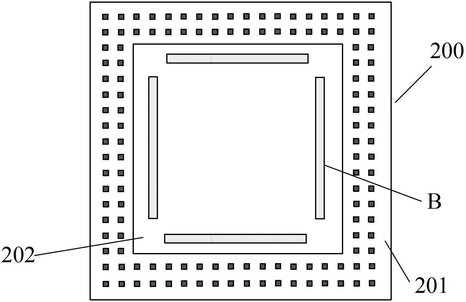
[0007] but, figure 2 The disadvantage of the semiconductor bond pad structure 200 shown is that after the trench (groove B) is made, the fluorine in the lower layer will volatilize and corrode the upper metal surface, causing circuit corrosion and other failures, and moisture will pass through the groove B into the underlying circuit layers, reducing the useful life of the circuit

Method used


Image

  • Semiconductor bond pad structure and integrated circuit
  • Semiconductor bond pad structure and integrated circuit
  • Semiconductor bond pad structure and integrated circuit

Examples


Embodiment Construction

[0021] In order to make the content of the present invention clearer and easier to understand, the content of the present invention will be described in detail below in conjunction with specific embodiments and accompanying drawings.

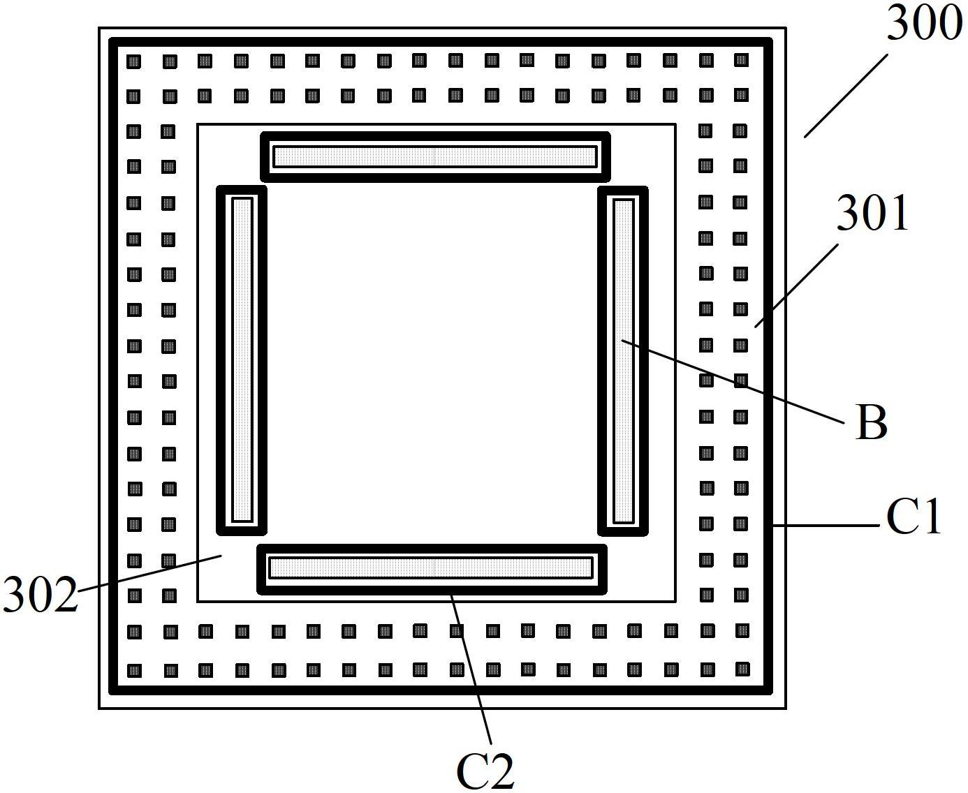
[0022] image 3 A semiconductor bond pad structure 300 according to an embodiment of the invention is schematically shown.

[0023] Such as image 3 As shown, a semiconductor bonding pad structure 300 according to an embodiment of the present invention includes a central portion 302 and a peripheral portion 301 .

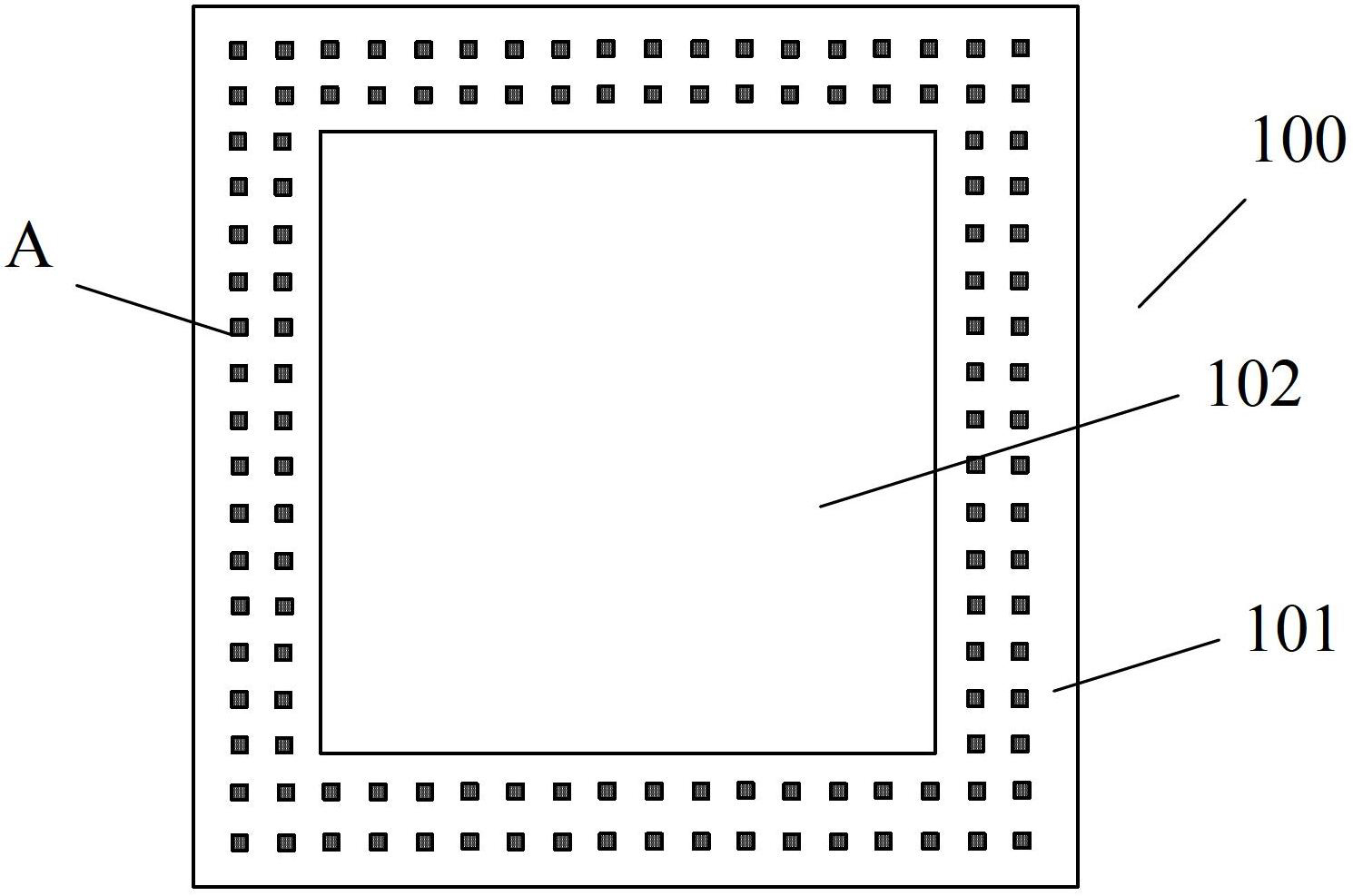
[0024] Wherein, preferably, a passivation layer is arranged on the surface of the peripheral portion 301 of the semiconductor bonding pad structure 300 , and a through hole A is formed in the peripheral portion 301 . Moreover, the central portion 302 of the semiconductor bonding pad structure 300 is an exposed metal film (generally an aluminum film). A through-hole matrix formed by a plurality of through-holes A is formed in the pe...


PUM


Abstract

The invention provides a semiconductor bond pad structure and an integrated circuit. The semiconductor bond pad structure comprises a central part and a periphery part, wherein the central part is an exposed metal thin film; a passivating layer is arranged on the surface of the periphery part and through holes are arranged in the periphery part; grooves are arranged at the periphery of the central part; and a groove tungsten wall is arranged at the periphery of each groove in the central part. According to the structure, the grooves are retained by the groove tungsten walls, so that fluorine volatilized from the lower layer is kept away and prevented from corroding the surface of upper layer metal and consequently circuit corrosion is avoided. Besides, according to the structure provided by the embodiment of the invention, each of the grooves is surrounded by the groove tungsten wall, so that water vapour is prevented by the groove tungsten walls from entering the lower layer structure and therefore the waterproof property is improved..

Description

technical field [0001] The invention relates to the field of semiconductor manufacturing, more specifically, the invention relates to a semiconductor bonding pad structure and an integrated circuit using the semiconductor bonding pad structure. Background technique [0002] Semiconductor packaging is an important process in the field of semiconductor manufacturing. Semiconductor packaging refers to the process of processing the tested wafers according to the product model and functional requirements to obtain independent chips. The packaging process is: the wafer from the wafer front-end process is cut into small chips after the dicing process, and then the cut chips are attached to the small islands of the corresponding substrate (lead frame) frame with adhesive , and then use ultra-fine metal (gold, tin, copper, aluminum, etc.) wires or conductive resin to connect the semiconductor bonding pad (Bond Pad) of the chip to the corresponding pin of the substrate to form the re...

Claims


Application Information

Patent Timeline
IPC IPC(8): H01L23/488
Inventor 黎坡
Owner SHANGHAI HUAHONG GRACE SEMICON MFG CORP
Learn More