Inter-vehicle charging device

A charging device and vehicle-to-vehicle technology, applied in circuit devices, battery circuit devices, electric vehicle charging technology, etc., can solve problems such as limited space and increased cost, and achieve the effects of efficient use, expansion of application scope, and shortening of rescue time.

Active Publication Date: 2012-09-19
FUJI ELECTRIC CO LTD
View PDF7 Cites 23 Cited by
  • Summary
  • Abstract
  • Description
  • Claims
  • Application Information

AI Technical Summary

Problems solved by technology

However, if this is the case, a separate DC/DC converter for fast charging i

Method used


Image

  • Inter-vehicle charging device
  • Inter-vehicle charging device
  • Inter-vehicle charging device

Examples


Embodiment Construction

[0051] Embodiments of the present invention will be described below with reference to the drawings.

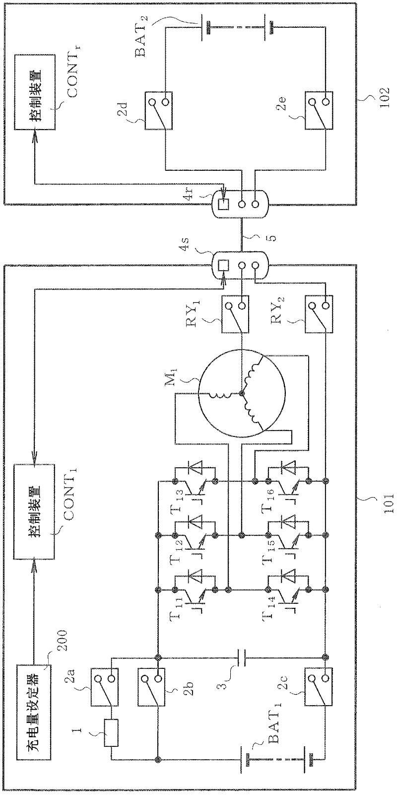
[0052] first, Figure 4 It is a configuration diagram of an electric vehicle drive system to which the first embodiment of the present invention is applied. In this system, electric vehicles and hybrid vehicles are used as rescue vehicles to charge the batteries of other rescue target vehicles (electric vehicles, etc.).

[0053] exist Figure 4 Among them, the electric vehicle drive system includes: electric motors such as permanent magnet synchronous motors used to drive electric vehicles M 1 ; Drive the motor M 1 The three-phase inverter INV; the battery BAT 1 ;Control device CONT 1 . In addition, 1 is a resistor for preventing inrush current, 2a, 2b, 2c, 2d, RY 1 、RY 2 is a relay, 3 is a capacitor, 4s is a standardized fast charging connector as a connection part, 7, 7u, 7v, 7w are current detectors, 8, 8a are voltage detectors, 10 is a magnetic pole position detect...


PUM


Abstract

The invention provides an inter-vehicle charging device. The invention provides a small-size low-cost inter-vehicle charging device capable of supplying the charging current suitable for a battery of a rescue object vehicle without using a DC/DC converter for fast charging. A rescue vehicle comprises a battery, an inverter; a motor for driving the vehicle and driven by the inverter; and a control device capable of managing the battery, controlling the inverter and controlling the charging of the batteries of the other rescue object vehicles. The inter-vehicle charging device for charging the battery of the rescue object vehicle using the rescue vehicle comprises a standardized connector for supplying the charging current output from a neutral point of the motor and one bus of positive, negative direct-current buses of the inverter to the battery and receiving and sending a control signal for charging the battery between the control device and the rescue object vehicle, and cables.

Description

technical field [0001] The present invention relates to an inter-vehicle charging device mounted on a vehicle such as an electric vehicle or a hybrid vehicle to charge a battery of another vehicle. Background technique [0002] In order to use vehicles such as electric vehicles or hybrid vehicles with sufficient battery power (hereinafter referred to as rescue vehicles) to rescue so-called electric vehicles such as electric vehicles that cannot run on their own due to exhausted batteries (hereinafter referred to as rescue target vehicles), as vehicles There is an invention described in Patent Document 1 as a prior art for charging and discharging between batteries. [0003] Hereinafter, the above-mentioned prior art will be described. [0004] Figure 19 It shows a main circuit configuration in which a rescue vehicle 101 with a sufficient remaining battery charge charges a rescue target vehicle 102 with a depleted battery. [0005] First, in order to suppress the battery B...

Claims


Application Information

Patent Timeline
IPC IPC(8): H02J7/00B60R16/02B60L50/16
CPCY02E60/12Y02T10/7077Y02T10/7005Y02T10/7241Y02T90/127Y02E60/10Y02T10/70Y02T10/72
Inventor 平形政树
Owner FUJI ELECTRIC CO LTD
Why Eureka
Try Eureka