
SCR (selective catalytic reduction) denitration dedusting device

A technology of denitrification and dust removal and dust collector, which is applied to the separation of dispersed particles, chemical instruments and methods, separation methods, etc., can solve the problem of increasing the power consumption and operating cost of induced draft fans, increasing the pressure head selection of boiler induced draft fans, and high temperature The complex structure of the cyclone separator and other problems achieve the effects of low additional cost, easy fabrication and installation, and reduced fly ash concentration

Active Publication Date: 2012-09-26
DONGFANG BOILER GROUP OF DONGFANG ELECTRIC CORP
View PDF6 Cites 36 Cited by
  • Summary
  • Abstract
  • Description
  • Claims
  • Application Information

AI Technical Summary

Problems solved by technology

[0007] In this patent, a high-temperature cyclone separator 6 is installed between the boiler 10 and the reactor 3, which can remove part of the fly ash in the flue gas and reduce the flue gas wear and tear on the denitration catalyst, but the high-temperature cyclone separator 6 needs a large pressure loss to achieve the purpose of separating the fly ash in the flue gas, and the pressure loss is as high as several hundred Pa. For the entire denitrification device with a pressure loss of only 600-900Pa, the increase The pressure loss of the denitrification device is obviously unacceptable, otherwise it will increase the pressure head selection of the induced draft fan of the boiler, thereby increasing the power consumption and operating cost of the induced draft fan
[0008]In addition, a high-temperature cyclone separator is installed between the boiler 10 and the denitrification reactor 3. The structure of the high-temperature cyclone separator itself is relatively complicated, and its investment cost is relatively high

Method used


Image

  • SCR (selective catalytic reduction) denitration dedusting device
  • SCR (selective catalytic reduction) denitration dedusting device
  • SCR (selective catalytic reduction) denitration dedusting device

Examples


Embodiment Construction

[0027] The following non-limiting examples serve to illustrate the invention.

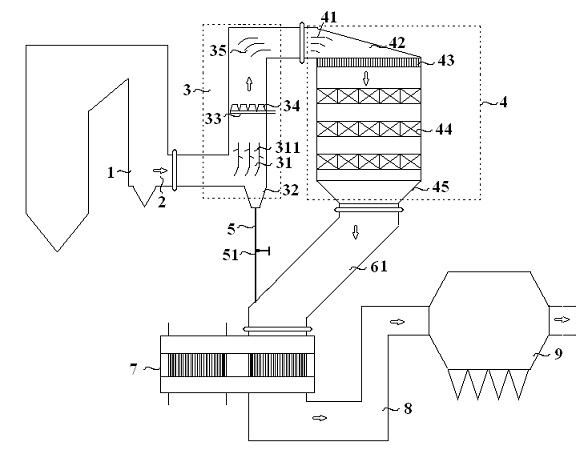
[0028] Such as image 3 As shown, the flue gas 2 of about 320-420°C flowing out from the outlet of the boiler economizer 1 enters the reactor inlet flue 3, and the upstream of the flue gas process of denitration and reducing agent injection in the reactor inlet flue 3 is from horizontal to vertical The bent 90° elbow (that is, the first 90° elbow in the figure) is provided with a dust removal guide device 31, and the flue gas passes through the dust removal guide device 31 to remove the ash and turn to the upward direction, and sprays with the reducing agent injection device 33 The incoming reducing agent ammonia is uniformly mixed by the reducing agent mixer 34 and then continues to move upward, and is guided by the second baffle 35 to enter the denitration reactor 4. The flue gas-ammonia mixture flows through the inlet baffle 41, the inlet cover 42, and uniformly passes through the catalyst layer 4...


PUM

PropertyMeasurementUnit
Angleaaaaaaaaaa

Abstract

The invention discloses an SCR (selective catalytic reduction) denitration dedusting device and relates to a dedusting device. The SCR denitration dedusting device comprises a reactor inlet flue which is communicated to the front of a denitration reactor. A dedusting guide device is arranged at a 90-degree elbow which is vertically bending upwards from the horizontal direction at the upstream of a denitration reducing agent injection flue gas in the reactor inlet flue, and comprises a guide mechanism and a dedusting mechanism, wherein the guide mechanism is smoothly communicated with a horizontal section and a vertical section of the 90-degree elbow in a bending manner, and a dust hopper and a dust outlet are arranged below the dedusting guide device on the 90-degree elbow. With low loss of pressure, equipment modification cost, running cost, the maximized benefit and the best dedusting effect are realized, and large-particle fly dust easy to block catalysts can be treated effectively.

Description

technical field [0001] The invention relates to a dust removal device, in particular to a dust removal device used in an SCR denitrification device. Background technique [0002] Selective Catalytic Reduction of NO x , referred to as SCR denitration process), is one of the more commonly used flue gas denitrification technologies at present. , the NO in the flue gas x Revert to harmless N 2 and H 2 O, to remove NO x the goal of. [0003] Conventional SCR denitrification process, such as attached figure 1 As shown, the flue gas 2 from the boiler economizer 1 passes through the flue baffle plate 63 at the entrance of the denitrification reactor 4, and mixes with the reducing agent ammonia injected by the reducing agent injection device 33, and after being uniformly mixed in the reducing agent mixer 34, Enter the denitrification reactor 4. Inside the denitrification reactor, the flue gas-ammonia mixture passes through the inlet mouth 42, flows through the catalyst 44 fro...

Claims


Application Information

Patent Timeline
IPC IPC(8): B01D45/08B01D53/90B01D53/56
Inventor 杨志忠叶茂
Owner DONGFANG BOILER GROUP OF DONGFANG ELECTRIC CORP
Features
  • Generate Ideas
  • Intellectual Property
  • Life Sciences
  • Materials
  • Tech Scout
  • Unparalleled Data Quality
  • Higher Quality Content
  • 60% Fewer Hallucinations
Learn More