High-speed cyclic gas-liquid mixed micro-nano foam generating device

A foam generating device, micro-nano technology, applied in the direction of mixers, mixing methods, fluid mixers, etc., can solve the problems of slow rotation speed, increased air flow, and insufficient consideration of the internal volume gas-liquid discharge hole ratio, etc. , to achieve the effect of large amount of bubbles and increased rotation speed

Inactive Publication Date: 2012-09-26
金强
View PDF3 Cites 14 Cited by
  • Summary
  • Abstract
  • Description
  • Claims
  • Application Information

AI Technical Summary

Problems solved by technology

[0002] In the previous devices (such as WO00/69550), there are the following deficiencies: 1. Because the ratio of the internal volume and the gas-liquid discharge hole is not fully consid...

Method used


Image

  • High-speed cyclic gas-liquid mixed micro-nano foam generating device
  • High-speed cyclic gas-liquid mixed micro-nano foam generating device
  • High-speed cyclic gas-liquid mixed micro-nano foam generating device

Examples


Embodiment Construction

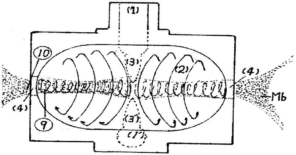
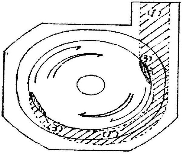
[0015] FIG. 1 is an explanatory diagram of the principle of a manufacturing apparatus.

[0016] Figure 1-(A) is a side view, and Figure 1-(B) is a cross-sectional view of Figure 1-(A).

[0017] Due to the high-speed hovering conditions and the gas, the specific gravity of the liquid is poor, the liquid generates a strong centrifugal force, and the gas generates a strong centripetal force so that the liquid and gas can be separated. Also, due to the huge speed difference between the front and rear parts of Figure 1-(A) ⑩, the strip-shaped gas part ⑨ is cut off continuously and stably. As a result, a large number of micro-nanofoam MNBs occurred. Bubbles with a diameter of 50nm to 20um occur near (4) in Fig. 1-(A), and are discharged out of the container.

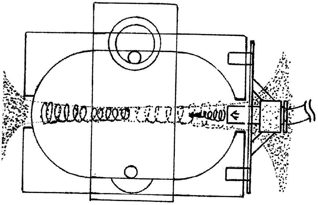
[0018] figure 2 This is a schematic diagram and an explanatory diagram of using the gas discharge hole as the gas input hole.

[0019] Explanation of use and application range

[0020] Small, medium, and large devices can...


PUM


Abstract

The invention discloses a high-speed cyclic gas-liquid mixed micro-nano foam generating device, which consists of two hemispherical containers and a cylindrical container which is connected with a water inlet pipe, hollow C-shaped pipes (3) and (3') are arranged on the cylindrical inner surface, and a circular hole (4) for spraying liquid to achieve the effects of micro-nano foam and an air conduit is formed at each of two hemispherical ends. Due to the hollow C-shaped pipes, the rotating speed of liquid is improved (so that super-micro thinning of foam is promoted), and the superfine foam generating rate is improved by 25 percent compared with the conventional superfine foam generating rate.

Description

technical field [0001] Though this invention adopts a spiral cut method among the recognized three foaming occurrences, it further develops the old spiral cut method to make the foam more refined. Moreover, it is a device that can easily adjust the input ratio of the generated liquid and gas. Background technique [0002] In the previous devices (such as WO00 / 69550), there are the following deficiencies: 1. Because the ratio of the internal volume and the gas-liquid discharge hole is not fully considered, the generated bubbles lack uniformity. 2. Due to the slow rotation speed, it is necessary to increase the flow of air. 3. Because it must be equipped with an air inlet pipe (such as figure 2 way), so once the conduit is damaged when used at sea or on rivers, the device will stop working. There are also many parts to be equipped, which is not ideal in terms of cost. Contents of the invention [0003] This device improves the above-mentioned shortcoming. The specific i...

Claims


Application Information

Patent Timeline
IPC IPC(8): B01F3/04B01F5/00B01F5/04C02F1/72C02F1/74C02F1/78
Inventor 金强
Owner 金强
Why Eureka
Try Eureka