Suction system and suction technology
An air extraction system and gas technology, which is applied to liquid variable volume machinery, machines/engines, mechanical equipment, etc., can solve the problems of complex structure of the air extraction system, and achieve the effects of cost reduction, high cost performance and simple structure.
- Summary
- Abstract
- Description
- Claims
- Application Information
AI Technical Summary
Problems solved by technology
Method used
Image

Examples
Embodiment 1
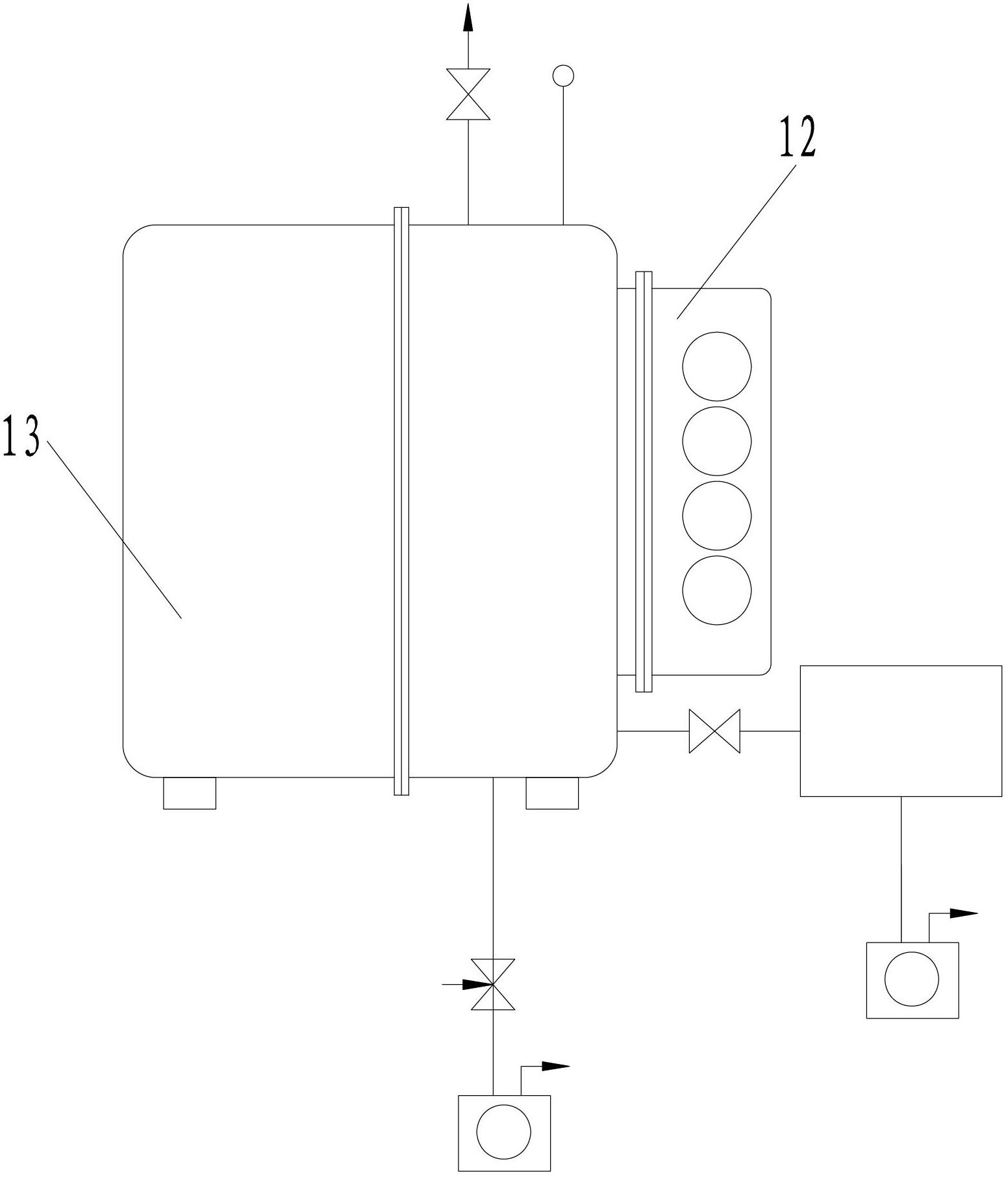
[0016] Such as figure 1 As shown, the pumping system provided by the embodiment of the present invention includes an arc titanium pump 12 and a vacuum chamber 13 , and the arc titanium pump 12 is directly communicated with the vacuum chamber 13 . In this way, the high vacuum valve between the arc titanium pump 12 and the vacuum chamber 13 can be omitted, the structure is simple, and the total cost of the pumping system is greatly reduced. Compatible with this pumping system, after the arc titanium pump 12 exhausts, before the vacuum chamber 13 is exposed to the atmosphere, the titanium target of the arc titanium pump 12 is cooled for a period of time, thereby reducing the oxidation loss of the titanium target surface and improving The service life of titanium target. This makes the air extraction system extremely cost-effective.
[0017] Usually, the titanium target is cooled by the cooling component of the arc titanium pump 12, which is convenient and quick. Wherein, the c...
Embodiment 2
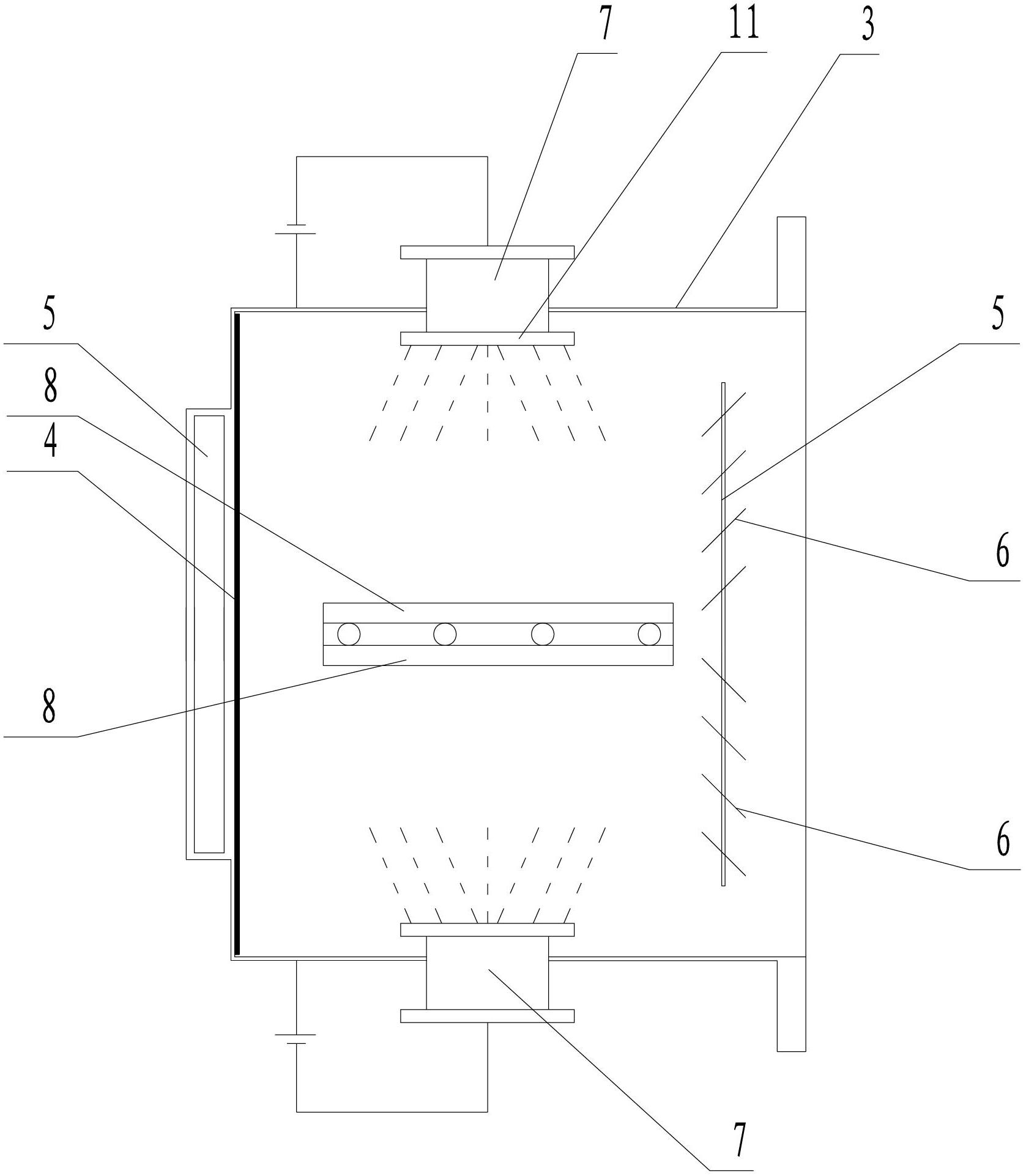
[0025] The difference from Embodiment 1 is that the arc titanium pump provided by the embodiment of the present invention includes two sets of cathode arc sources 7 and two gas main collecting plates 8, and the two gas main collecting plates 8 are arranged on the opposite two sets of cathodes. between arc sources 7, such as image 3 shown. Here, the cathode arc source 7 is in one-to-one correspondence with the gas main trapping plate 8, and the distance between the two should be large enough, preferably 200-400mm, so that the titanium film deposited on the gas main trapping plate 8 is uniform, It is beneficial to increase the adsorption probability of the titanium film. Due to the addition of a set of cathode arc sources 7 and the matching main gas trapping plate 8, compared with the traditional arc titanium pump of the same size, the pumping speed of the arc titanium pump is increased by about 40%. In order to further increase the pumping speed of the electric arc titanium ...
Embodiment 3
[0028] The difference from the second embodiment is that the gas main collecting plate 15 in the embodiment of the present invention is formed by a plurality of mutually parallel sub-plates 16 arranged obliquely, such as Figure 4 shown. Wherein, the ratio of the width of the sub-boards 16 to the distance between adjacent sub-boards is preferably 1.4-3 times, and the inclination angle of the sub-boards 16 is preferably 40-75°.
PUM
 Abstract
Description
Claims
Application Information
 - R&D
- Intellectual Property
- Life Sciences
- Materials
- Tech Scout
- Unparalleled Data Quality
- Higher Quality Content
- 60% Fewer Hallucinations
Browse by: Latest US Patents, China's latest patents, Technical Efficacy Thesaurus, Application Domain, Technology Topic, Popular Technical Reports.
© 2025 PatSnap. All rights reserved.Legal|Privacy policy|Modern Slavery Act Transparency Statement|Sitemap|About US| Contact US: help@patsnap.com