Micro laser scanning device and portable terminal thereof

A technology of laser scanning device and portable terminal, applied in electromagnetic radiation induction, television, telephone structure and other directions, can solve the problems of high power consumption of scanning mechanism, increase the volume of laser scanning device, etc., and achieve small size, flexible layout, and reduced size The effect of the overall volume

Active Publication Date: 2012-09-26
广州市钛码电子科技有限公司
View PDF7 Cites 5 Cited by
  • Summary
  • Abstract
  • Description
  • Claims
  • Application Information

AI Technical Summary

Problems solved by technology

In order to ensure that the recovered light signal has sufficient luminous flux, the area of ​​the oscillating mirror cannot be made too small, usually about 11mm*14mm, and the larger area of ​​the oscillating mirror, in addition to increasing the volume of the laser scanning device, also limits the improvement of the scanning frequency , while the power consumption of the scanning mechanism is also relatively large
Generally, the scanner with the above structure has a scanning frequency of only about 20Hz

Method used


Image

  • Micro laser scanning device and portable terminal thereof
  • Micro laser scanning device and portable terminal thereof
  • Micro laser scanning device and portable terminal thereof

Examples


Embodiment Construction

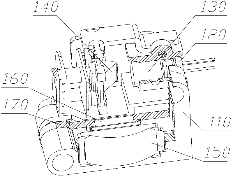
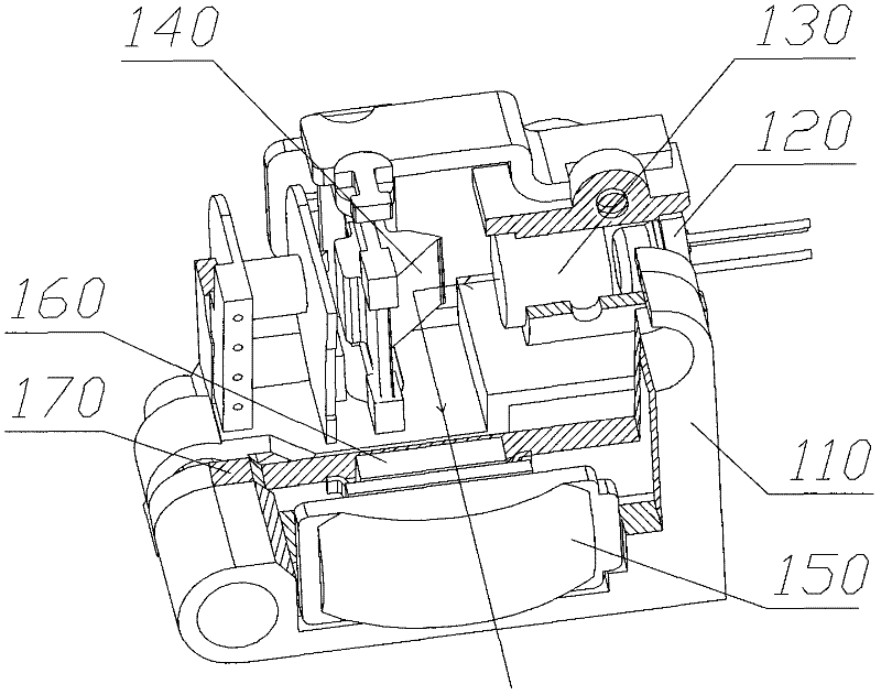
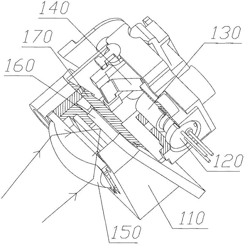
[0022] For those skilled in the art, the above content has made detailed and sufficient disclosures of related technical solutions. The technical solution of the present invention has multiple implementations in terms of spatial layout (the light receiving component and the light emitting component can be located on the same side or different sides of the data processing module, and the light receiving component can be located on the top, bottom, and left side of the light emitting component , right and other directions), and here only one of them is taken as an example for a detailed introduction. For those skilled in the art, the implementation of the present invention is not limited thereto.

[0023] The patterns mentioned in the present invention include barcode patterns composed of black bars and white spaces, or other patterns with different reflectivity to laser light due to different colors or different gray scales.

[0024] The micro laser scanning module structure of...


PUM


Abstract

The invention discloses a micro laser scanning device and a portable terminal of the micro laser scanning device, wherein the micro laser scanning device comprises a light emitting component, a light receiving component and a data processing module; the light emitting component comprises a laser emitting module, a line collecting mirror and a wabbler mirror; the wabbler mirror is used for reflecting laser beam emitted by the line collecting mirror to a scanning object; the light receiving component comprises a photovoltaic conversion module and a spot collecting mirror; the spot collecting mirror is used for directly receiving and collecting lights reflected by the detected object to an illuminated face of the photovoltaic conversion module; the photovoltaic conversion module converts a light signal into an electrical signal; the data processing module processes the received electrical signal to obtain corresponding image information. The portable terminal comprises a micro laser scanning device, wherein the corresponding image information scanned by the micro laser scanning device is displayed by the display module of the portable terminal. The micro laser scanning device has the advantages of fast scanning speed, flexible layout and small power consumption.

Description

technical field [0001] The invention relates to a laser scanning device, in particular to a miniature laser scanning device and a portable terminal thereof. Background technique [0002] The current laser scanning device adopts the optical structure of "backward reception", that is, the optical paths of the scanning light and the receiving light basically overlap. In this optical structure, because the oscillating mirror used to scan the outgoing light is also used to reflect and recycle the light. In order to ensure that the recovered light signal has sufficient luminous flux, the area of ​​the oscillating mirror cannot be made too small, usually about 11mm*14mm, and the larger area of ​​the oscillating mirror, in addition to increasing the volume of the laser scanning device, also limits the improvement of the scanning frequency , At the same time, the power consumption of the scanning mechanism is also relatively large. Generally, the scanner with the above-mentioned st...

Claims


Application Information

Patent Timeline
Patent Type & Authority Applications(China)
IPC IPC(8): G06K7/10H04N5/225H04M1/21
Inventor 郑锡俊郑锡海
Owner 广州市钛码电子科技有限公司
Why Eureka
Try Eureka