Derailment detector unit with extended sensitivity

A detector, technology for rail vehicles, in the field of derailment detector units with extended sensitivity

Active Publication Date: 2012-09-26
KNORR BREMSE SYST FUR SCHIENENFAHRZEUGE GMBH
View PDF7 Cites 7 Cited by
  • Summary
  • Abstract
  • Description
  • Claims
  • Application Information

AI Technical Summary

Problems solved by technology

However, only severe acceleration peaks can be detected by known derailment detectors, because its mass-spring system is only suitable for severe peak-type accelerat...

Method used


Image

  • Derailment detector unit with extended sensitivity
  • Derailment detector unit with extended sensitivity
  • Derailment detector unit with extended sensitivity

Examples


Embodiment Construction

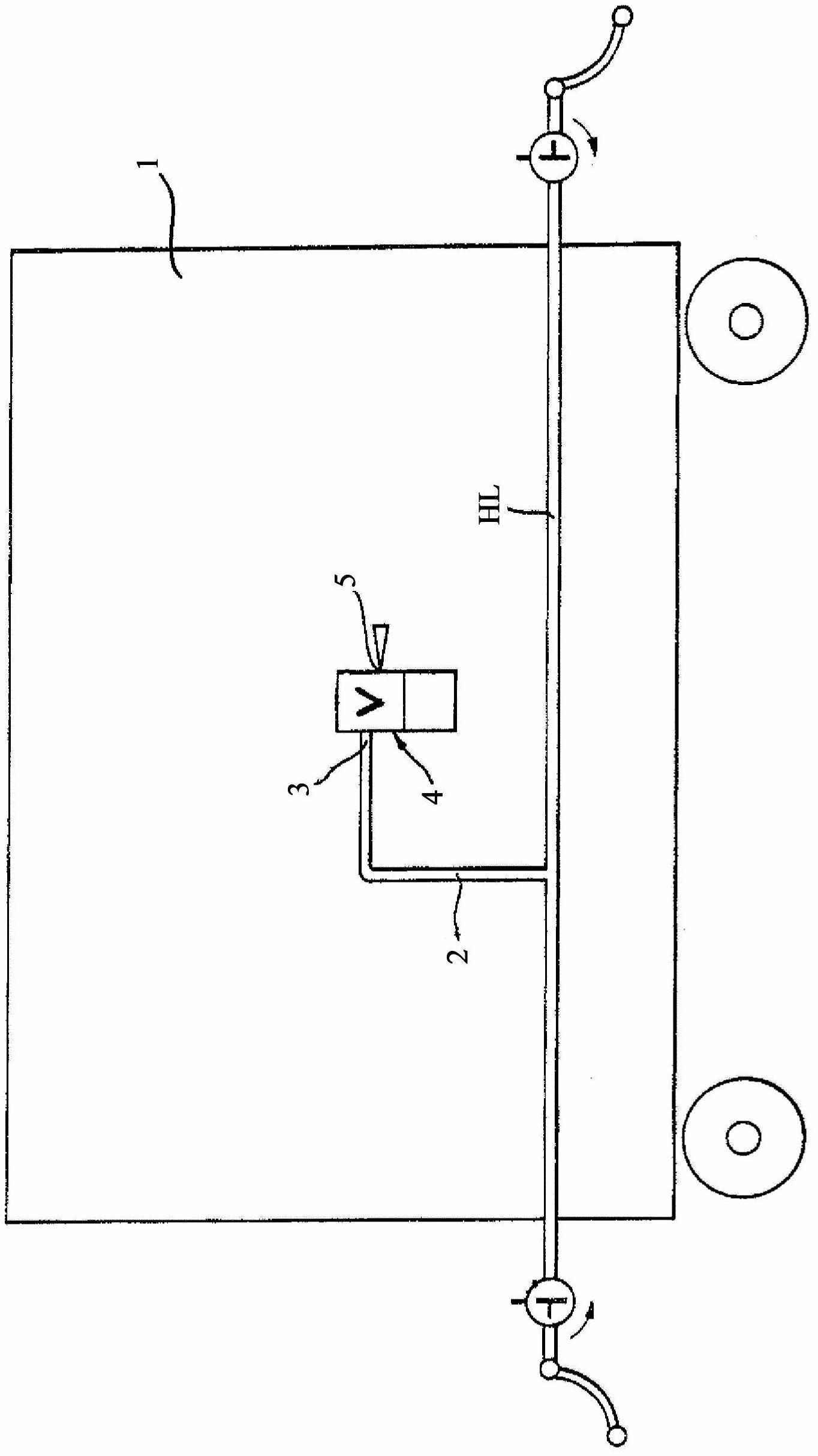
[0020] figure 1 A wagon 1 of a rail vehicle is shown. The main brake pipe HL of the compressed air brake system, not further shown, extends from one end of the wagon to its other end. A branch conduit 2 connects the main brake pipe HL of the compressed air brake system to the air inlet 3 of the derailment detector unit 4 . The derailment detector unit 4 detects defined vertical acceleration peaks on the rail vehicle in order to convert them into actuation shocks of the emergency brake valve assembly which are used to activate the service brake via the exhaust port 5 of the derailment detector unit 4 Pipe HL exhaust to drive the compressed air brake system.

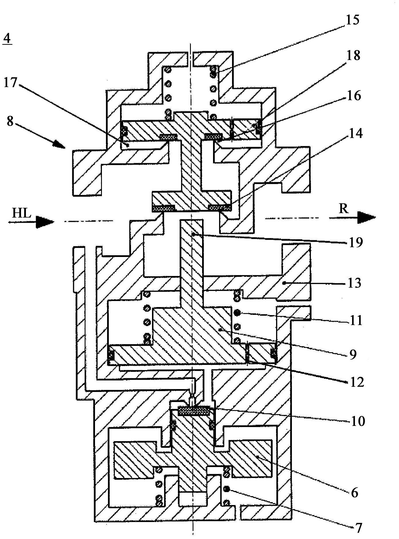
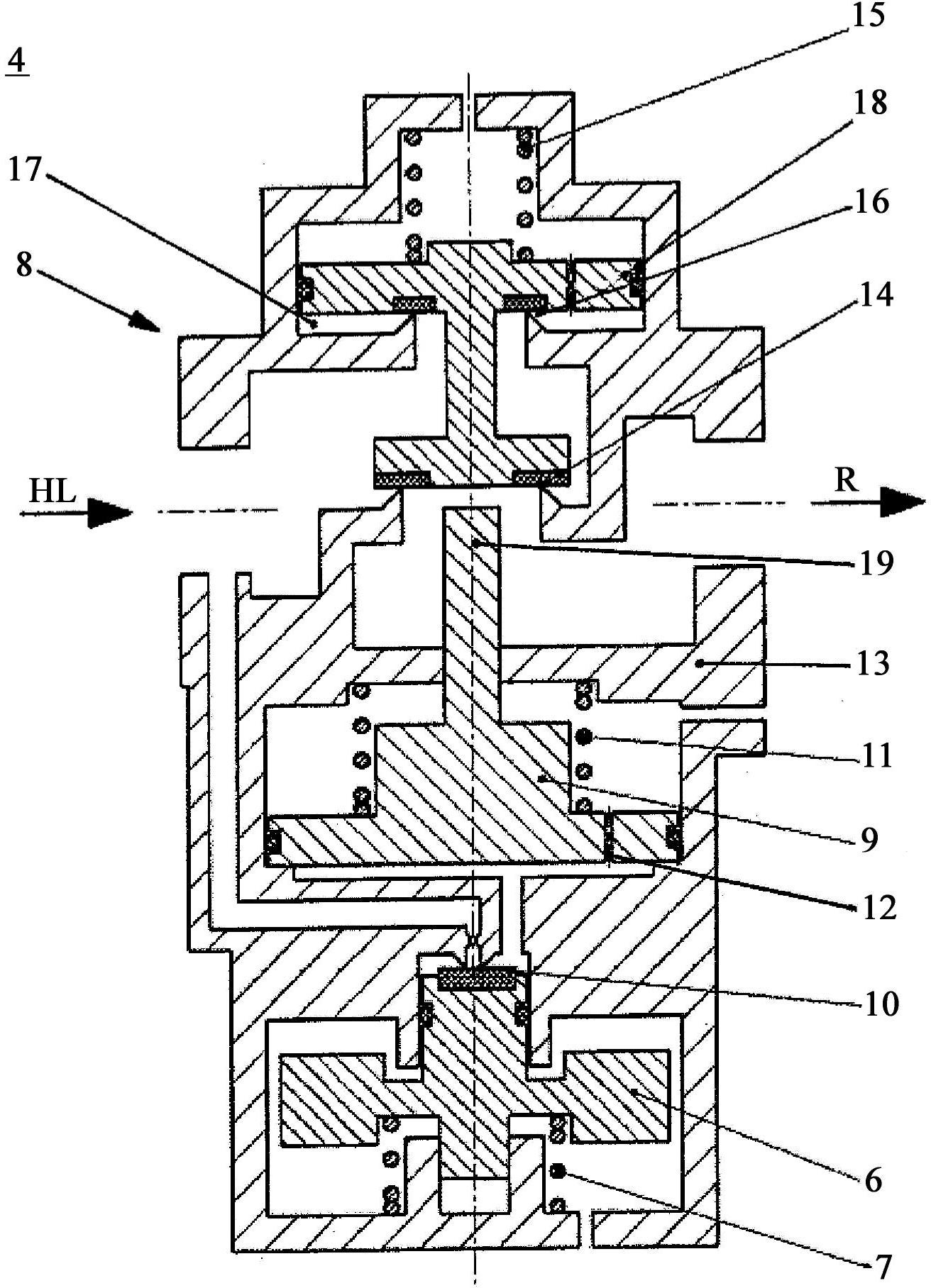
[0021] see figure 2 , The derailment detector unit 4 includes a vertically movable filling block 6 connected in series with a compression spring 7 . This mass-spring assembly converts the effective vertical acceleration peak into an actuation shock of the mechanically linked emergency brake valve assembly 8 for actuat...


PUM


Abstract

The invention relates to a derailment detector unit (4) for sensing vertical acceleration peaks on a rail vehicle comprising a vertical movable filling mass (6) connected in series with a compression spring (7) for transforming significant vertical acceleration peaks into an actuation stroke of a mechanically coupled emergency brake valve assembly (8) for actuating a compressed air brake system by venting a main break pipe (HL), wherein the emergency brake valve assembly (8) is actuated via a trigger mass piston (9) preloaded due to vertical motion of the filling mass (6), in order to form a double-mass triggering unit for the emergency brake valve assembly (8).

Description

technical field [0001] The invention relates to a derailment detector unit for detecting a peak vertical acceleration on a rail vehicle, the derailment detector unit comprising a vertically movable filler mass connected in series with a compression spring for converting the effective peak vertical acceleration into The actuation impulse of the mechanically linked emergency brake valve assembly used to actuate the compressed air brake system by venting the main brake line (HL). Furthermore, the invention relates to a rail vehicle with a compressed air braking system, which rail vehicle is provided with such a derailment detector unit. Background technique [0002] The derailment detector unit may be used on any rail vehicle where emergency braking may be activated by venting the main brake pipe, in particular on freight cars carrying dangerous goods. Derailment of a rail vehicle is a rare, unique and undesirable event, so immediate emergency braking must be activated. Varia...

Claims


Application Information

Patent Timeline
IPC IPC(8): B61F9/00B60T7/12
CPCB60T17/228F02F3/26B60T13/665B61F9/00B60T7/124
Inventor 加博尔・奥奇科
Owner KNORR BREMSE SYST FUR SCHIENENFAHRZEUGE GMBH
Why Eureka
Try Eureka