Vessel neck construction of a pressure vessel

A pressure vessel and neck technology, applied in the field of the vessel neck structure of pressure vessels, can solve problems such as sealing problems

Active Publication Date: 2012-09-26
考特斯机械科技(佛山)有限公司
View PDF10 Cites 16 Cited by
  • Summary
  • Abstract
  • Description
  • Claims
  • Application Information

AI Technical Summary

Problems solved by technology

[0009] Such sealing can be problematic especially when inner containers or plastic inner containers are produced by extrusion blow molding

Method used


Image

  • Vessel neck construction of a pressure vessel
  • Vessel neck construction of a pressure vessel
  • Vessel neck construction of a pressure vessel

Examples


Embodiment Construction

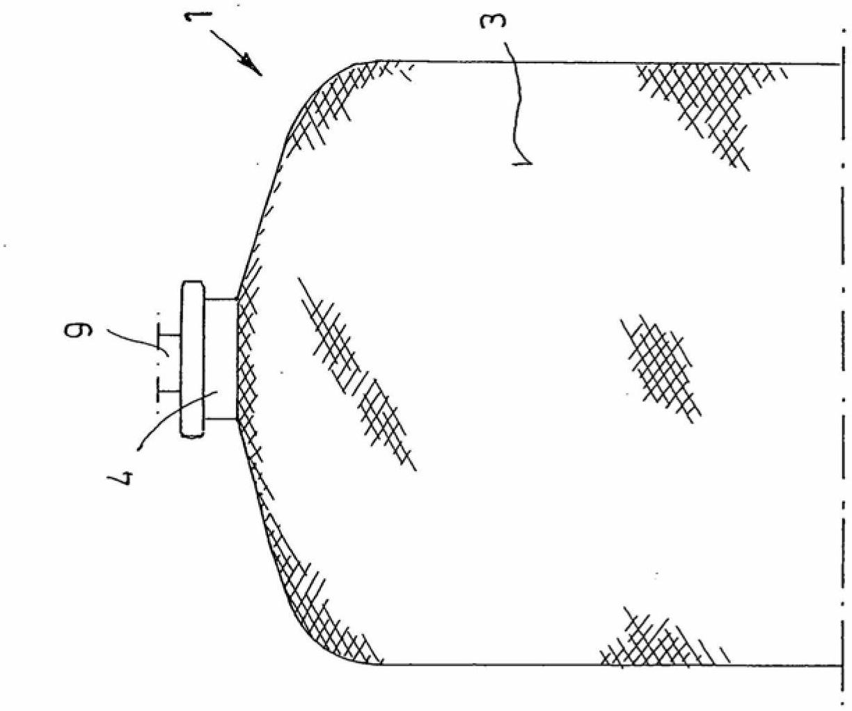
[0036] figure 1 The pressure vessel 1 shown in has a plastic inner container 2 preferably obtained by extrusion blow molding, which is surrounded by a support shell 3 made of fiber reinforcement embedded in a matrix made of synthetic resin.

[0037] Although according to the preferred embodiment the plastic inner container 2 is obtained by extrusion blow molding, it can also be obtained by a thermoforming process or by a rotational sintering process (thin shell moulding). Polyethylene, polypropylene, polyester, polyurethane, polyoxymethylene (POM), thermoplastic elastomer (TPE) or the like are conceivable as materials for the plastic inner container 2 .

[0038] The support cover can consist of carbon fibers, aramid threads, glass threads or the like. The support shell is preferably produced by winding the plastic inner container 2 with resin-impregnated fibres / threads. This procedure is known per se.

[0039] To simplify the illustration, the bearing cap 3 is only shown in...


PUM


Abstract

The invention relates to a pressure vessel for storing liquid or gaseous media. The pressure vessel (1) comprises a plastic inner vessel (2), at least one neck piece (4) connected thereto as a separate piece, said neck piece being arranged on the vessel neck in the area of the vessel opening (8), and a support casing (3) that at least partially encloses the plastic inner vessel (2) and the neck piece (4). The neck piece (4) is provided with means for accommodating a connection fitting (9). The pressure vessel according to the invention is characterized by an insert (5), which forms at least part of the vessel neck and which forms a sealing seat for the fitting (9) to be inserted into the neck piece (4).

Description

technical field [0001] The invention relates to a pressure vessel for storing liquid or gaseous media, said pressure vessel comprising a plastic inner vessel having at least one neck part which is not integrally connected to the plastic inner vessel and an at least partially The support cap surrounds the plastic inner container and the neck part, which is arranged on the container neck in the region of the container opening, and which is provided with means for accommodating connecting accessories. Background technique [0002] Such a pressure vessel is known, for example, from DE 2152123. The high-pressure gas tank described there comprises a shape-stable, rotationally symmetrical, gas-tight, cylindrical inner container in its central region, which has two coaxially sleeved on the bottom of the inner container from the outside. head piece (Polstücke) or neck piece and a sheath made of continuous thread and hardened plastic laminated, wound onto the inner container with the...

Claims


Application Information

Patent Timeline
Patent Type & Authority Applications(China)
IPC IPC(8): F17C13/06
CPCY02E60/321F17C2205/0305F17C2209/2127F17C2203/0663F17C2209/227F17C2203/0658F17C2260/036F17C2203/0636F17C2209/221F17C13/06F17C2223/0123F17C2203/0604F17C2209/2118F17C2201/0104F17C2205/0323F17C2209/2109Y02E60/32
Inventor M·霍尔巴赫S·瓦尔布勒尔
Owner 考特斯机械科技(佛山)有限公司
Why Eureka
Try Eureka