High-pressure rotational flow mixing device

A technology of mixing device and high-pressure swirling flow, which is applied in the direction of fluid mixer, mixer, dissolution, etc., to achieve the effect of large velocity gradient, sufficient and uniform mixing, and high mixing efficiency

Inactive Publication Date: 2012-10-03
CHINA UNIV OF PETROLEUM (EAST CHINA)
View PDF2 Cites 8 Cited by
  • Summary
  • Abstract
  • Description
  • Claims
  • Application Information

AI Technical Summary

Problems solved by technology

But so far, the research on the mixing of solid and liquid or solid and gas in the cyclone has not been reported at home and abroad.

Method used


Image

  • High-pressure rotational flow mixing device
  • High-pressure rotational flow mixing device
  • High-pressure rotational flow mixing device

Examples


Embodiment 1

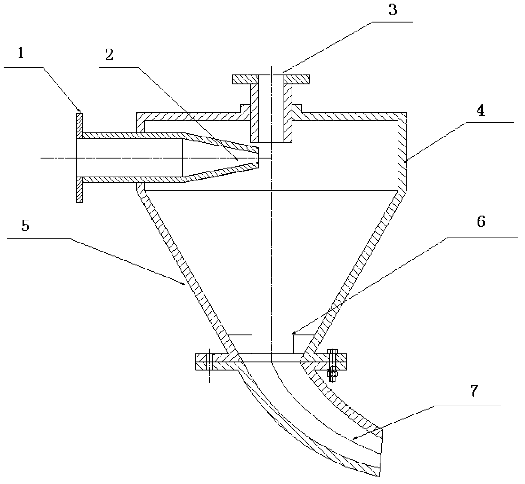
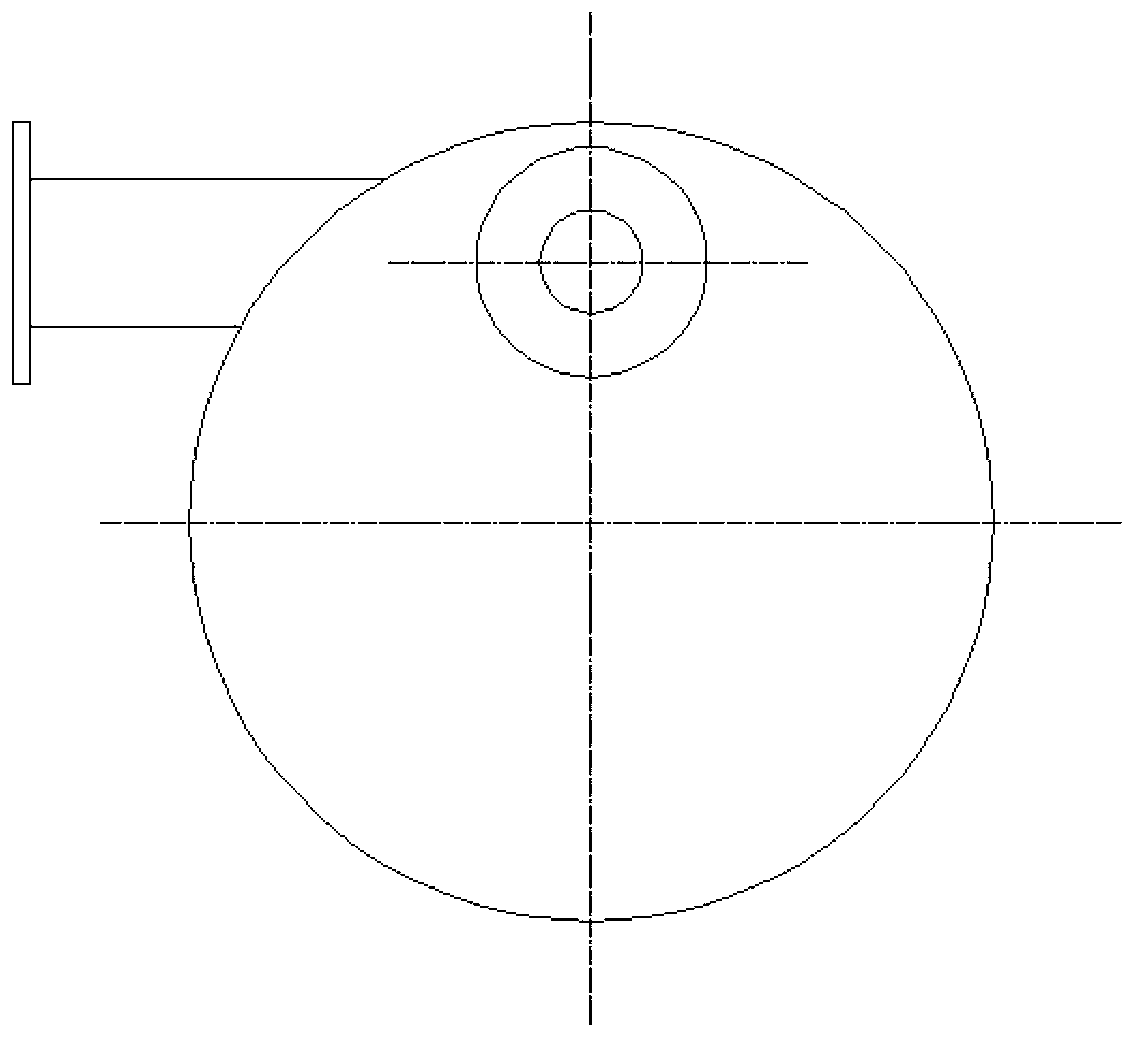
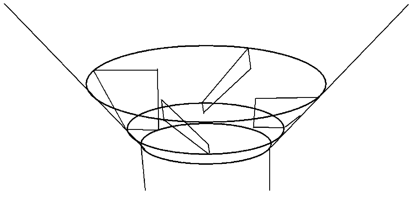
[0013] Embodiment 1: as Figure 1-3 As shown, the main mixing chamber of the high-pressure swirl mixing device is composed of a cylindrical mixing chamber 4 and a conical mixing chamber 5 connected in series. The fluid inlet pipe 1 is connected to the cylindrical mixing chamber 4, and the fluid inlet pipe 1 is provided with a nozzle 2 with a pressure greater than 10 MPa. A solid phase feeding port 3 is installed above the cylindrical mixing chamber 4, and the axis of the solid phase feeding port 3 is perpendicular to the axis of the nozzle 2. A mixing baffle 6 is designed at the outlet of the conical mixing chamber 5, and the mixing baffle 6 is composed of 2 blades distributed at an angle of 20° between the outlet of the conical mixing chamber and the horizontal plane. The outlet of the conical mixing chamber 5 is connected to the inlet of the steady flow elbow 7, and the steady flow elbow 7 adopts a variable diameter structure, and its inlet diameter is D 1 , the outlet dia...

Embodiment 2

[0014] Embodiment 2: as Figure 1-3 As shown, the main mixing chamber of the high-pressure swirl mixing device is composed of a cylindrical mixing chamber 4 and a conical mixing chamber 5 connected in series. The fluid inlet pipe 1 is connected to a cylindrical mixing chamber 4 . The fluid inlet pipe 1 is provided with a nozzle 2 with a pressure resistance greater than 10 MPa. A solid phase feeding port 3 is installed above the cylindrical mixing chamber 4, and the axis of the solid phase feeding port 3 is perpendicular to the axis of the nozzle 2. A mixing baffle 6 is designed at the outlet of the conical mixing chamber 5, and the mixing baffle 6 is composed of 4 blades distributed at an angle of 45° between the outlet of the conical mixing chamber and the horizontal plane. The outlet of the conical mixing chamber 5 is connected to the inlet of the steady flow elbow 7, and the steady flow elbow 7 adopts a variable diameter structure, and its inlet diameter is D 1 , the out...

Embodiment 3

[0015] Embodiment 3: as Figure 1-3 As shown, the main mixing chamber of the high-pressure swirl mixing device is composed of a cylindrical mixing chamber 4 and a conical mixing chamber 5 connected in series. The fluid inlet pipe 1 is connected to a cylindrical mixing chamber 4 . The fluid inlet pipe 1 is provided with a nozzle 2 with a pressure resistance greater than 10 MPa. A solid phase feeding port 3 is installed above the cylindrical mixing chamber 4, and the axis of the solid phase feeding port 3 is perpendicular to the axis of the nozzle 2. A mixing baffle 6 is designed at the outlet of the conical mixing chamber 5, and the mixing baffle 6 is composed of 6 blades distributed at an angle of 60° between the outlet of the conical mixing chamber and the horizontal plane. The outlet of the conical mixing chamber 5 is connected to the inlet of the steady flow elbow 7, and the steady flow elbow 7 adopts a variable diameter structure, and its inlet diameter is D 1 , the out...


PUM


Abstract

The invention provides a high-pressure rotational flow mixing device. The main mixing chamber of the high-pressure rotational flow mixing device is formed by connecting and combining a cylindrical mixing chamber and a conical mixing chamber in series; a liquid inlet pipe is connected with the cylindrical mixing chamber; the liquid inlet pipe is internally provided with a nozzle which can resist a pressure of larger than 10MPa; a solid phase charging opening is formed above the cylindrical mixing chamber; the axis of the solid phase charging opening is perpendicular to that of the nozzle; the outlet of the conical mixing chamber is provided with a mixing baffle plate; the baffle plate consists of 2-6 blades which are distributed at the outlet and have the angle from 20 degrees to 60 degrees relative to the horizontal plane; and the outlet of the conical mixing chamber is connected with the inlet of a constant-current elbow pipe; the elbow pipe is of a diameter-changing structure, wherein the elbow pipe inlet diameter D1/the elbow pipe outlet diameter D2=1.5-1.8, and the curvature radius of the central axis of the elbow pipe R/D=3.0-3.5. The inner wall of the mixing chamber is sprayed with a wear-resistant material mixed with solid particles, so that the abrasive resistance of a chamber body can be improved, the concavity of the spraying surface can be increased, the turbulent condition in the mixing chamber can be enhanced, and the mixing efficiency can be improved.

Description

Technical field: [0001] The invention relates to a device for mixing solid phase and liquid phase or solid phase and gas phase, in particular to a device for mixing solids such as dust and particles with liquid or gas at construction sites in fields such as oil and gas fields and coal gas fields. Background technique: [0002] At present, the commonly used mixers in the industrial field mainly include pipeline mixers and static mixers. Pipeline mixers are generally composed of pipes, nozzles, vortex chambers, perforated plates or special-shaped plates, etc. The mixing methods are divided into three types: nozzle type, vortex type, perforated plate or special-shaped plate type; It is developed from plate and special-shaped plate mixers. The mixer has two kinds of fixed helical blades, left-handed and right-handed. When the fluid passes through the helical blades, the flow direction changes and turbulence occurs to achieve mixing. Pipeline mixers are too small in size and hav...

Claims


Application Information

Patent Timeline
Patent Type & Authority Applications(China)
IPC IPC(8): B01F5/02B01F15/02
Inventor 程远方刘钰川董丙响袁征杨柳黄浩勇吴百烈徐太双
Owner CHINA UNIV OF PETROLEUM (EAST CHINA)
Why Eureka
Try Eureka