Encased concrete composite shear wall embedded with dense steel plate beams between concrete-filled steel tube columns and construction method thereof

A technology of concrete-filled steel tube columns and concrete-filled steel tubes, which is applied to walls, building components, buildings, etc., can solve the problems of insufficient bearing capacity, ductility and energy consumption, delay cracking and crack development, suppress out-of-plane instability, and improve vertical effect on bearing capacity

Inactive Publication Date: 2012-10-03
BEIJING UNIV OF TECH
View PDF1 Cites 6 Cited by
  • Summary
  • Abstract
  • Description
  • Claims
  • Application Information

AI Technical Summary

Problems solved by technology

[0005] The purpose of the present invention is to provide a new type of steel-concrete composite shear wall that consumes earthquake input structural energy and improves the seismic performance of the structure. It is mainly used in the shear wall structure or cylinder structure of high-rise buildings or large complex multi-story buildings. Solve the problem of insufficient bearing capacity, ductility and energy consumption under earthquake action

Method used


Image

  • Encased concrete composite shear wall embedded with dense steel plate beams between concrete-filled steel tube columns and construction method thereof
  • Encased concrete composite shear wall embedded with dense steel plate beams between concrete-filled steel tube columns and construction method thereof
  • Encased concrete composite shear wall embedded with dense steel plate beams between concrete-filled steel tube columns and construction method thereof

Examples


Embodiment Construction

[0022] The present invention will be further described below in conjunction with specific embodiment:

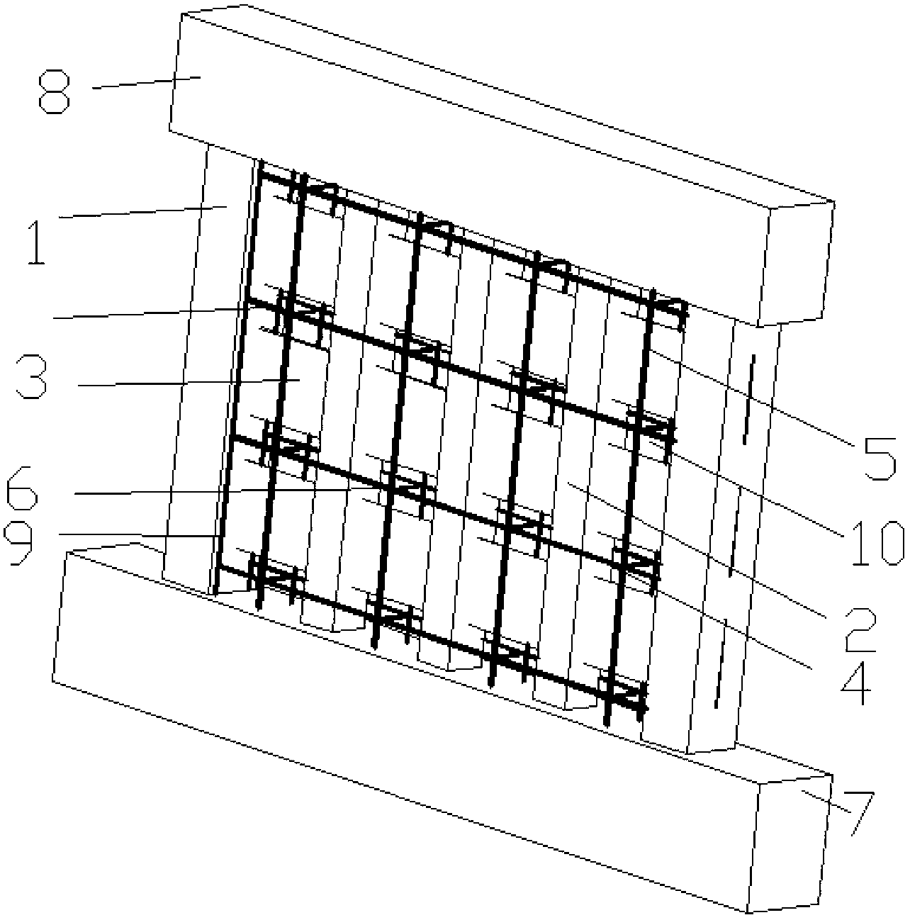
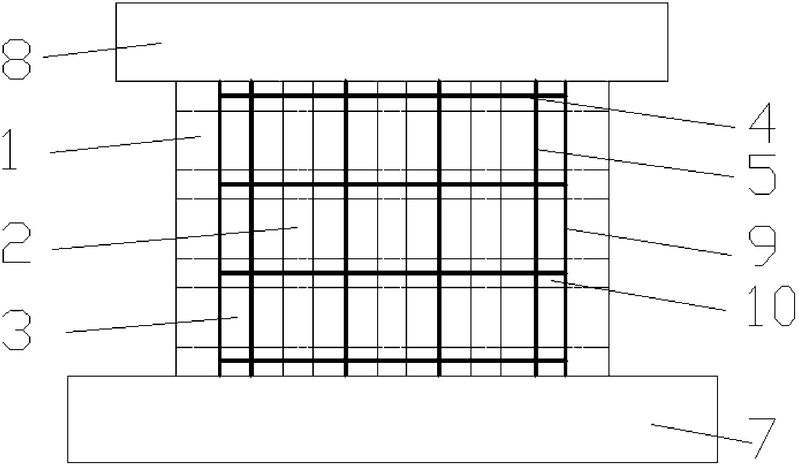
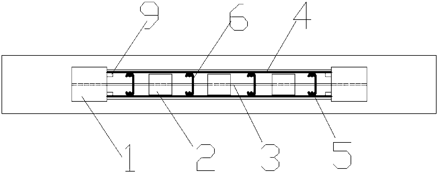
[0023] The structural diagram of a structural unit of a composite shear wall with steel plate dense beams embedded between concrete filled steel tube columns and outsourcing concrete composite shear wall is as follows figure 1 , figure 2 and image 3 shown.

[0024] Steel tube concrete frame columns 1 are arranged at both ends of the reinforced concrete shear wall; the steel tube wall of the steel tube concrete frame column 1 is welded to the steel bar connecting rib 9 for fixing the horizontally distributed steel bars 4 of the wall; the upper and lower sides of the steel tube concrete frame column 1 Set the upper frame beam 8 and the lower frame beam 7; set the steel tube concrete core column 2 in the direction parallel to the steel tube concrete frame column 1 inside the reinforced concrete shear wall; the steel plate dense beam 3 passes through the steel tube concrete ...


PUM


Abstract

An encased concrete composite shear wall embedded with dense steel plate beams between concrete-filled steel tube columns and a construction method thereof belong to the field of steel-concrete composite shear walls. The encased concrete composite shear wall is composed of concrete-filled steel tube frame columns, concrete-filled steel tube core columns, dense steel plate beams and a reinforced concrete shear wall with an I-shaped wall section. The encased concrete composite shear wall embedded with dense steel plate beams between concrete-filled steel tube columns is formed by the following steps that the concrete-filled steel tube frame columns are arranged at both ends of the reinforced concrete shear wall; the concrete-filled steel tube core columns are arranged between the concrete-filled steel tube frame columns; the level parallel dense steel plate beams are arranged between the concrete-filled steel tube frame columns and the concrete-filled steel tube core columns and between the concrete-filled steel tube core columns along the height direction of the reinforced concrete shear wall; the dense steel plate beams pass through the concrete-filled steel tube columns to be welded with steel tubes on intersection lines; shear wall reinforcing steel bars are bound; and concrete is poured. The encased concrete composite shear wall has the advantages that the bearing capability is enhanced, the ductility and the energy dissipation of the shear wall are enhanced due to multi-defenses, and the earthquake resistant capability is excellent. The encased concrete composite shear wall also has the advantages of convenience in construction and easiness in operation, and can be used in high-rise or large complex multi-storey buildings.

Description

technical field [0001] The invention relates to a steel-steel-concrete composite shear wall embedded with dense steel beams and outsourcing concrete composite shear walls between concrete-filled steel pipe columns and a manufacturing method thereof, which belongs to a novel steel-concrete composite shear wall that consumes earthquake-input structure energy and improves the seismic performance of the structure and its manufacturing method. The method belongs to the field of steel-concrete composite shear walls. Background technique [0002] At present, with the development of social production and the needs of human activities, there are more and more modern high-rise and super high-rise buildings, and the requirements for the seismic performance of shear walls are also getting higher and higher. Shear walls and core tubes composed of shear walls are the most critical vertical system for high-rise buildings to resist earthquakes, and they bear most of the seismic action of th...

Claims


Application Information

Patent Timeline
Patent Type & Authority Applications(China)
IPC IPC(8): E04B2/58E04B2/64E04G21/00
Inventor 董宏英刘恒超曹万林蒋峰张建伟
Owner BEIJING UNIV OF TECH
Why Eureka
Try Eureka