Shaping template for shear wall in deformation joint position of high-rise building

A technology for high-rise buildings and shaped templates, which is applied to the preparation of building components on site, construction, and building construction. Problems such as the surface distortion of the force wall 21 achieve the effects of improving the quality of molding and appearance, shortening the construction period, and increasing the number of turnovers

Inactive Publication Date: 2012-10-03
THE 4TH CONSTR ENG CO LTD OF CHINA RAILWAY NO 4 ENG GRP
View PDF6 Cites 9 Cited by
  • Summary
  • Abstract
  • Description
  • Claims
  • Application Information

AI Technical Summary

Problems solved by technology

[0003] In order to solve the problem that traditional polystyrene boards are currently used to fill the deformation joints 20, the surface of the shear wall 21 is easily distorted and deformed, the thickness of the protective layer of the reinforcement 14 of the shear wall is insufficient, the width of the deformation joints 20 does not meet the design requirements, and even the concrete on both sides of the root of the wall is connected. , so that the deformation joint 20 cannot play the role of free deformation of the buildings on both sides. At the same time, the forming quality of the concrete of the shear wall 21 on both sides of the deformation joint 20 is greatly improved. Formwork for force walls

Method used


Image

  • Shaping template for shear wall in deformation joint position of high-rise building
  • Shaping template for shear wall in deformation joint position of high-rise building
  • Shaping template for shear wall in deformation joint position of high-rise building

Examples


Embodiment

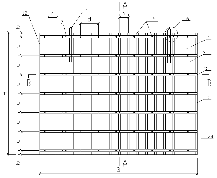
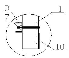
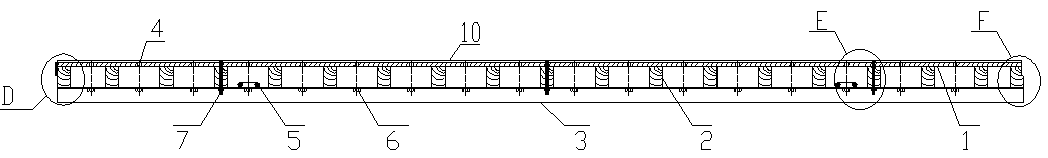
[0028] see figure 1 and figure 2 , the stereotyped formwork 24 that is used for the high-rise building deformation joint position shear wall comprises rectangular bamboo plywood 1, and the periphery of one side of bamboo plywood 1 is fixedly installed with square wood bars respectively, forms a square frame, and the bamboo plywood 1 in the square frame Upright square wooden secondary flute 2 is evenly distributed on the side, and square wooden secondary flute 2 is perpendicular to the long side of bamboo plywood 1; Vertical to the square wooden secondary flute 2, and parallel to the long side of the bamboo plywood 1; three short bolts 7 are arranged on the channel steel main flute 3, and the three short bolts 7 pass through the corresponding square wooden secondary flute 2 to connect the bamboo glue plate 1, see Figure 4 , Figure 5 , Figure 6 , Figure 7 and Figure 9 There are through holes evenly distributed on the web in the notch of channel steel main flute 3, a...


PUM


Abstract

The invention relates to a shaping template for a shear wall in a deformation joint position of a high-rise building. The shaping template comprises a rectangular bamboo plywood, wherein square wood sticks are respectively arranged on the periphery of one side surface of the bamboo plywood, so as to form a square frame; erect square timber secondary ribs are uniformly distributed on the side surface of the bamboo plywood in the square frame; channel steel main ribs are uniformly formed on the outer sides of the square timber secondary ribs; the channel steel main ribs are perpendicular to the square timber secondary ribs; more than two short bolts connected with the bamboo plywood are arranged on the channel steel main ribs; through holes are uniformly formed in web plates in groove mouths of the channel steel main ribs; a screw cap is arranged at each through hole; two inverted U-shaped hoisting rings are uniformly arranged on a long edge on one side of the bamboo plywood, a steel plate strip is arranged on the long edge of one side of the other side surface of the bamboo plywood in a parallel manner, and a horizontal rubber seal strip is arranged on the long edge of the other side of the other side surface of the bamboo plywood in a parallel manner; in addition, a vertical rubber seal strip is arranged on a short edge of one side of the bamboo plywood in a parallel manner, and an inner concave groove-shaped groove is formed on the short edge of the other side of the bamboo plywood in a parallel manner. The shaping template is simple to process, can achieve integral lifting, improves the working efficiency, has high construction speed, and shortens the construction period.

Description

technical field [0001] The invention belongs to the technical field of building construction technology, and in particular relates to a shear wall template at the deformation joint position of a high-rise building. Background technique [0002] High-rise buildings have become the mainstream development direction of the current construction industry. For super-long high-rise structures (generally exceeding 45m), deformation joints 20 ( Figure 10 ) (including settlement joints, expansion joints or anti-seismic joints), and the usual construction method of deformation joints is to fill the deformation joints 20 with polystyrene foam boards instead of templates. Although this construction method is simple, it has the following problems: (1) It is difficult to ensure the thickness of the concrete protective layer of the reinforcement 14 of the shear wall on both sides of the polystyrene board; (2) Since the density of the polystyrene board is too small, and the lateral pressure a...

Claims


Application Information

Patent Timeline
Patent Type & Authority Applications(China)
IPC IPC(8): E04G13/00
Inventor 李明董燕囝张坤彭宏伟汪元元
Owner THE 4TH CONSTR ENG CO LTD OF CHINA RAILWAY NO 4 ENG GRP
Why Eureka
Try Eureka